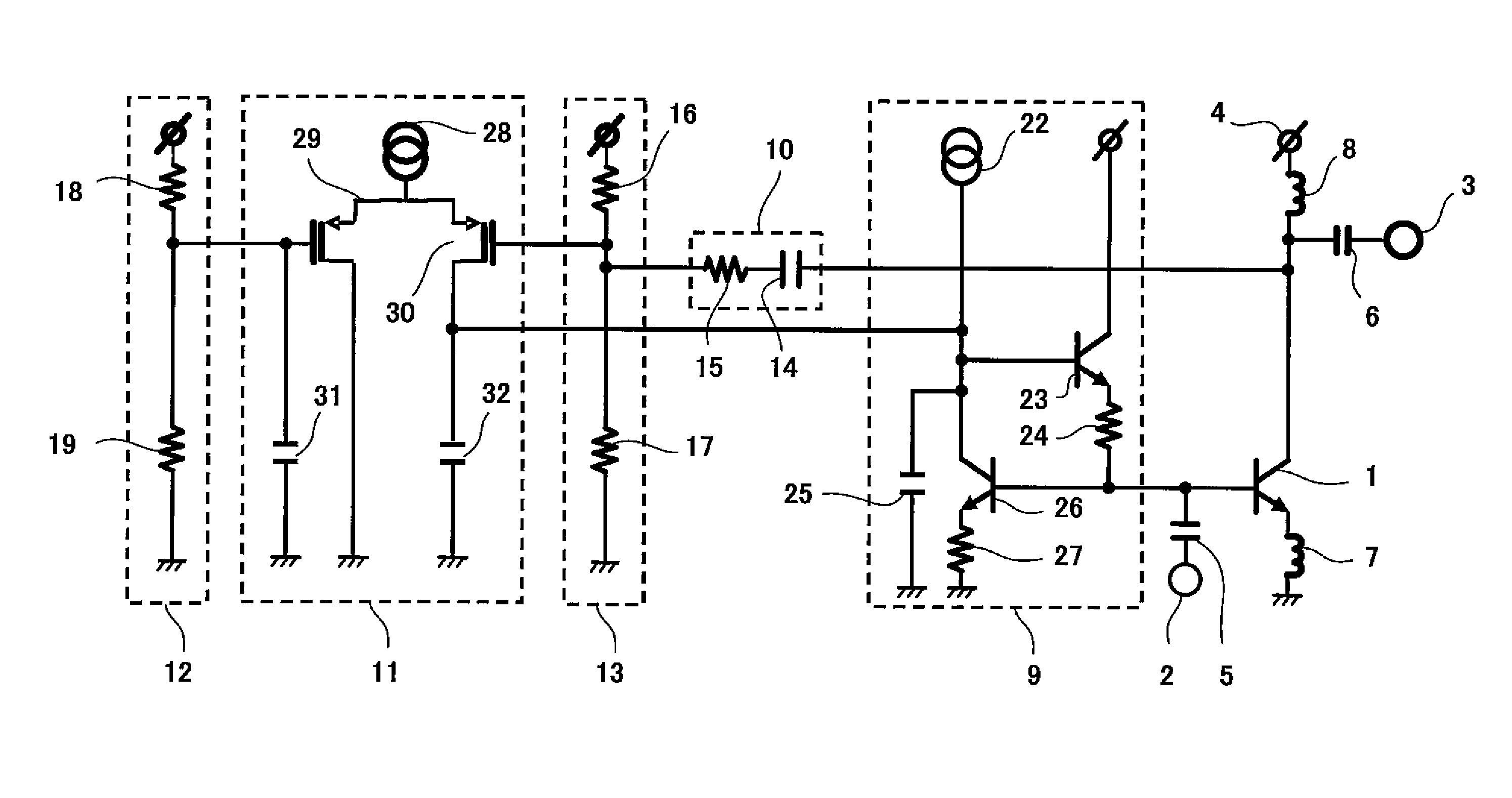
Low-noise amplifier
a low-noise amplifier and amplifier technology, applied in the direction of low-noise amplifiers, gain control, negative-feedback circuit arrangements, etc., can solve the problems of low-noise amplifiers and inability to achieve stably advantages, and achieve the effect of reducing the gain of transistors, increasing the bias current, and easy setting
- Summary
- Abstract
- Description
- Claims
- Application Information
AI Technical Summary
Benefits of technology
Problems solved by technology
Method used
Image
Examples
embodiment 1
[0028](Embodiment 1)
[Configuration of Low-Noise Amplifier]
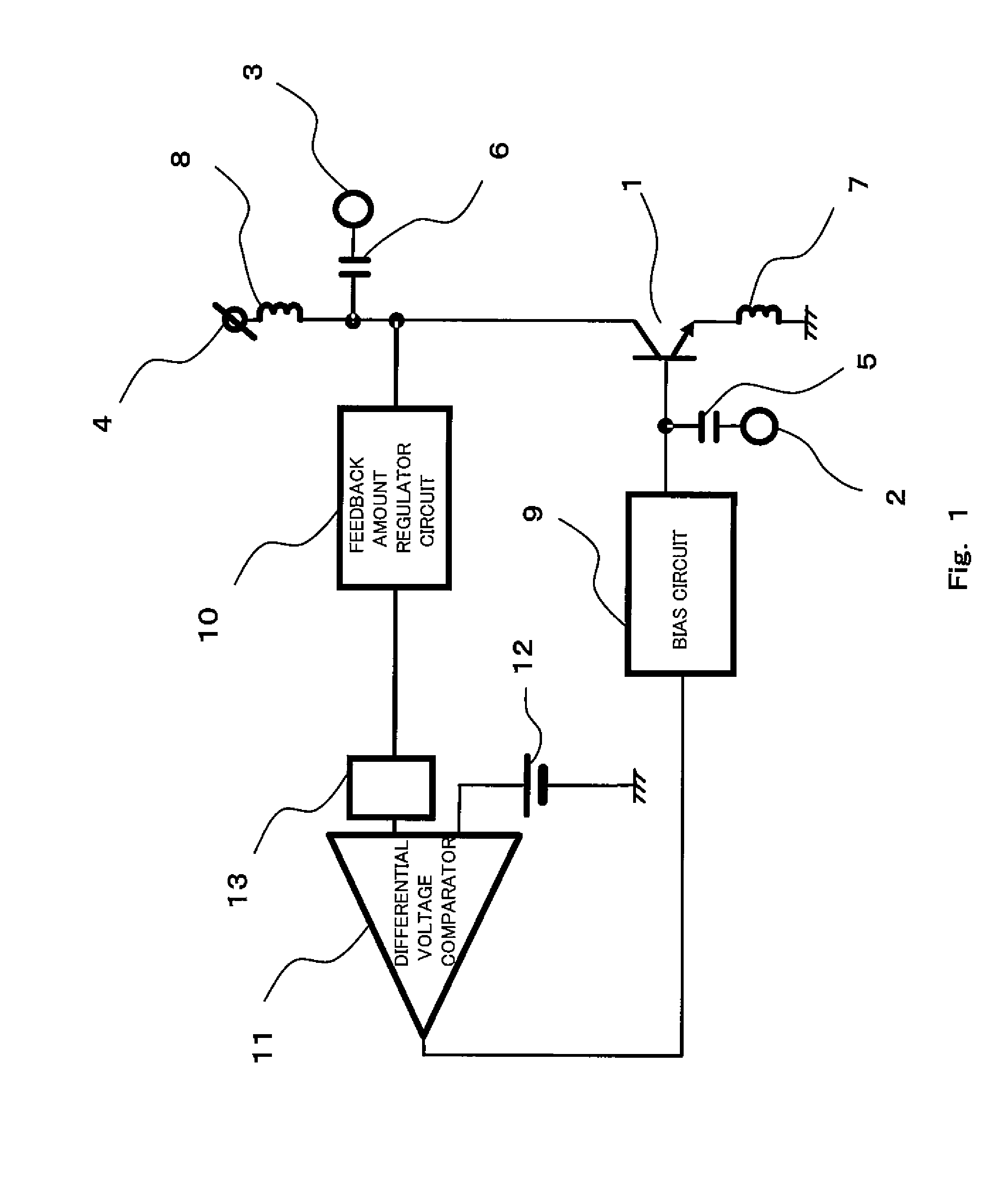
[0029]FIG. 1 is a circuit diagram showing an exemplary configuration of a low-noise amplifier according to Embodiment 1 of the present invention. Referring to FIG. 1, the low-noise amplifier includes a NPN-type transistor 1, an input terminal 2 connected to a base of the NPN-type transistor 1 via a DC cut capacitor 5, an output terminal 3 connected to a collector of the NPN-type transistor 1 via a DC cut capacitor 6, an inductor 7 connected to an emitter of the NPN-type transistor 1 and to a ground, and an inductor 8 connected to a collector of the NPN-type transistor 1 and to a power supply terminal 4.
[0030]The NPN-type transistor 1 constitutes an emitter ground circuit. The NPN-type transistor 1 amplifies a signal input from the input terminal 2 to the base via the DC cut capacitor 5 to generate an output signal and outputs the generated signal to the output terminal 3 via the DC cut capacitor 6.
[0031]The DC cut capacitor 5...
embodiment 2
[0066](Embodiment 2)
[0067]FIG. 5 is a circuit diagram showing an exemplary configuration of a low-noise amplifier according to Embodiment 2 of the present invention.
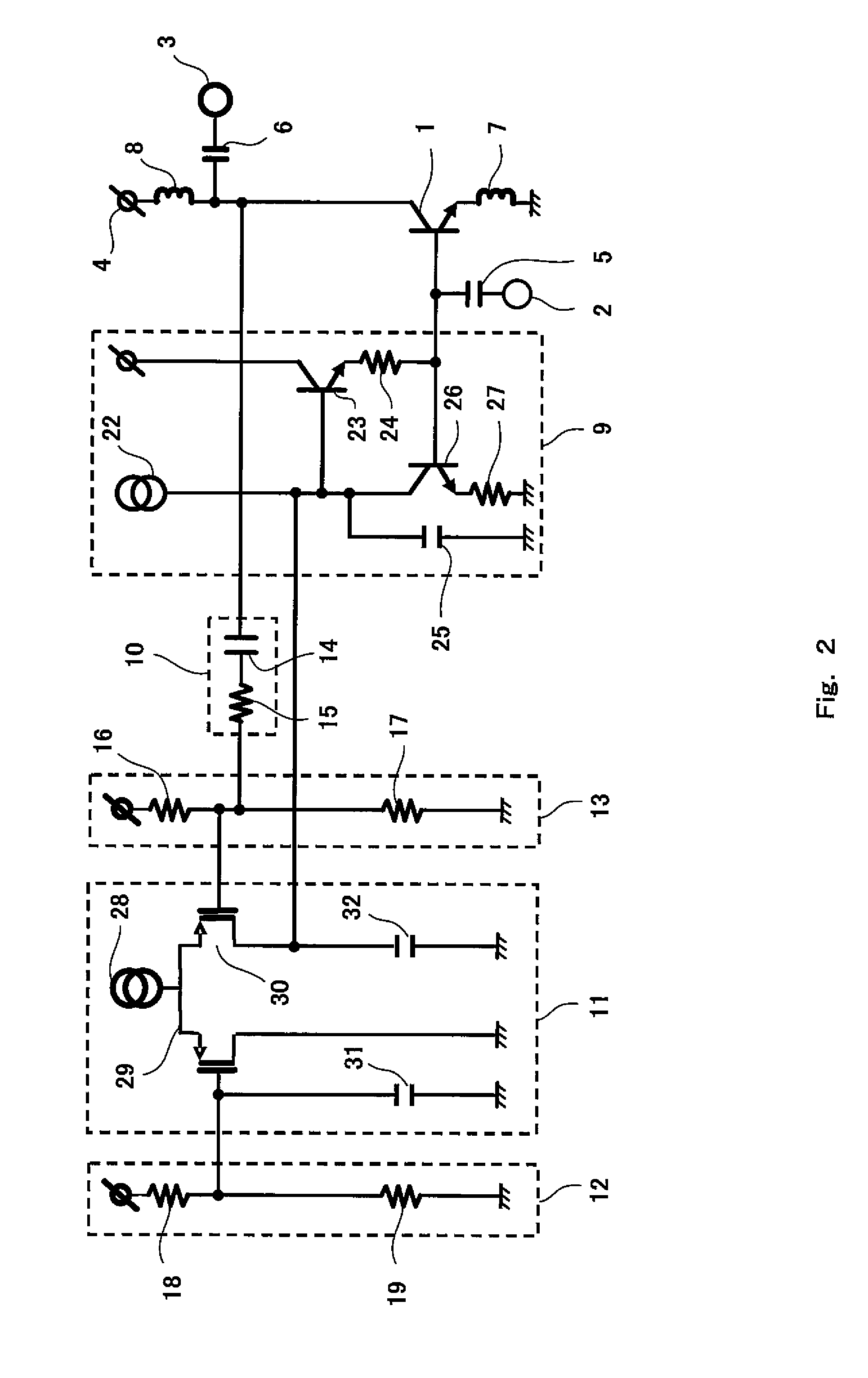
[0068]The low-noise amplifier of FIG. 5 is different from the low-noise amplifier of FIG. 1 in that current mirror circuits 20 and 21 are connected to each other between the output of the differential voltage comparator 11 and the input of the bias circuit 9, in the low-noise amplifier of FIG. 1 of FIG. 5. The current mirror circuit 20 includes a pair of NMOSFETs, while the current mirror circuit 21 includes a pair of PMOSFETs. In Embodiment 2, the exemplary configuration of FIG. 2 may be used as the configuration of the bias circuit 9, the feedback amount regulator circuit 10, the first input bias circuit 12, the second input bias circuit 13 and the differential voltage comparator 11.
[0069]In a case where the level of the disturbing wave signal increases up to a level at which the gain of the NPN-type transistor 1 is su...
PUM
 Abstract
Description
Claims
Application Information
 - R&D
- Intellectual Property
- Life Sciences
- Materials
- Tech Scout
- Unparalleled Data Quality
- Higher Quality Content
- 60% Fewer Hallucinations
Browse by: Latest US Patents, China's latest patents, Technical Efficacy Thesaurus, Application Domain, Technology Topic, Popular Technical Reports.
© 2025 PatSnap. All rights reserved.Legal|Privacy policy|Modern Slavery Act Transparency Statement|Sitemap|About US| Contact US: help@patsnap.com


