
Method and system for controlling filter operation

a filter and operation method technology, applied in the direction of electric control of exhaust treatment, separation process, instruments, etc., can solve the problems of reducing engine fuel economy, restricting exhaust flow, and increasing backpressur

Active Publication Date: 2013-02-26
FILTER SENSING TECH
View PDF38 Cites 64 Cited by
  • Summary
  • Abstract
  • Description
  • Claims
  • Application Information

AI Technical Summary

Benefits of technology

This patent describes a system for controlling a particle filter in an engine. The system uses microwave resonance techniques to monitor the loading of the filter and detect any failures or malfunctions. The control system can initiate regeneration of the filter and alert the operator if there is a failure. The control system is also able to estimate the amount of ash in the filter and modify engine operation to optimize performance. Sensors and a control unit are used to make these estimates, which can help maintain optimal engine performance.

Problems solved by technology

As particulate matter accumulates in the filter, exhaust flow is restricted and backpressure increases.
This increased backpressure reduces engine fuel economy, and in severe cases, may cause engine malfunction or damage.
Excessive soot accumulation in the particulate filter may lead to high internal filter temperatures during regeneration, increasing filter thermal stress, and, in some cases, resulting in filter cracking or melting.
On the other hand, regenerating the filter too frequently results in unnecessary fuel economy penalties.
Ash accumulation displaces soot, reducing the filter's soot storage capacity.
Ash deposits may alter the distribution of the soot accumulated in the filter.
Following extended use, the amount of ash accumulated in the particulate filter may significantly exceed the amount of soot and affect the filter's performance.
Filter failures may occur via the formation of cracks or melting, for example.
Pressure drop measurements alone provide only an indirect and imprecise measure of material accumulation in the particulate filter, and suffer from a number of disadvantages.
Further, the distribution of the accumulated ash and soot also affects the pressure drop measurement, and this distribution may change with time, particularly as the filter becomes loaded with ash.
Pressure drop measurements are also unable to distinguish between soot and ash accumulation in the filter, the latter of which introduces additional error in soot load estimates based on pressure drop.
Additionally, many types of filters exhibit a non-linear pressure drop response and pressure drop hysteresis depending upon the loading state and history of the filter.
Further, the inability of these systems to directly monitor ash levels in the filter requires the filters to be periodically inspected, resulting in vehicle or machine down-time, regardless of the actual filter ash level.
Additionally, pressure-drop based measurements are unable to detect all but the most catastrophic of filter failures, and, in most cases, can not meet stringent on-board diagnostic requirements.
Furthermore, when used with cleaner burning fuels, (compared to the fuel with which the models were initially calibrated) the models tend to over-predict filter soot loading, resulting in unnecessary filter regenerations and fuel economy penalties.
The combined use of predictive models and filter pressure drop measurements does little to overcome the deficiencies listed above.
These shortcomings lead to inefficient system operation, fuel economy penalties, increased filter thermal cycling and fatigue, and reduced filter service life.
These measurement systems suffer from the deficiency that the amount of soot accumulated on the particulate filter is not necessary equivalent to the amount of soot entering the filter, as some level of passive regeneration may take place, depending on exhaust conditions.
Further, exhaust gas soot sensors provide no information on ash accumulation or soot and ash distribution in the DPF.
In addition, many of these sensors suffer form soot fouling, consume excessive amounts of energy, and are subject to error introduced by exhaust temperature, exhaust gas velocity, and other factors.
However, such systems cannot determine the spatial distribution of soot content within the particulate filter.
(a) Prior art systems are unable to monitor the spatial distribution of material accumulated in the filter. Ash accumulation in the filter displaces soot and alters its distribution. Further, non-uniform flow conditions may also result in non-uniform material accumulation.
(b) All known filter load monitoring systems initiate filter regeneration based on some average total filter soot load. Locally high soot loads cannot be detected by systems that are not capable of measuring material distribution in the filter.
(c) Previous microwave- and RF-based filter loading systems cannot simultaneously detect both soot and ash accumulation in the filter over all exhaust conditions.
(d) These systems do not detect filter failures or malfunctions, which is important to ensure the filter is operating as required.
(e) These systems do not detect malfunctions or failures of individual components, such as sensors, for example, that may be required for correct operation of the filter.
(f) Microwave and RF-based measurement systems are strongly affected by moisture content and water vapor present in the exhaust gas and on the filter, which must be accounted for to reduce error in the measurement.
(g) Previous filter load monitoring systems fail to communicate with existing engine and exhaust sensors to provide feedback control capabilities useful to modify engine operation to optimize the combined engine and after-treatment system performance.

Method used


Image

  • Method and system for controlling filter operation
  • Method and system for controlling filter operation
  • Method and system for controlling filter operation

Examples


Embodiment Construction

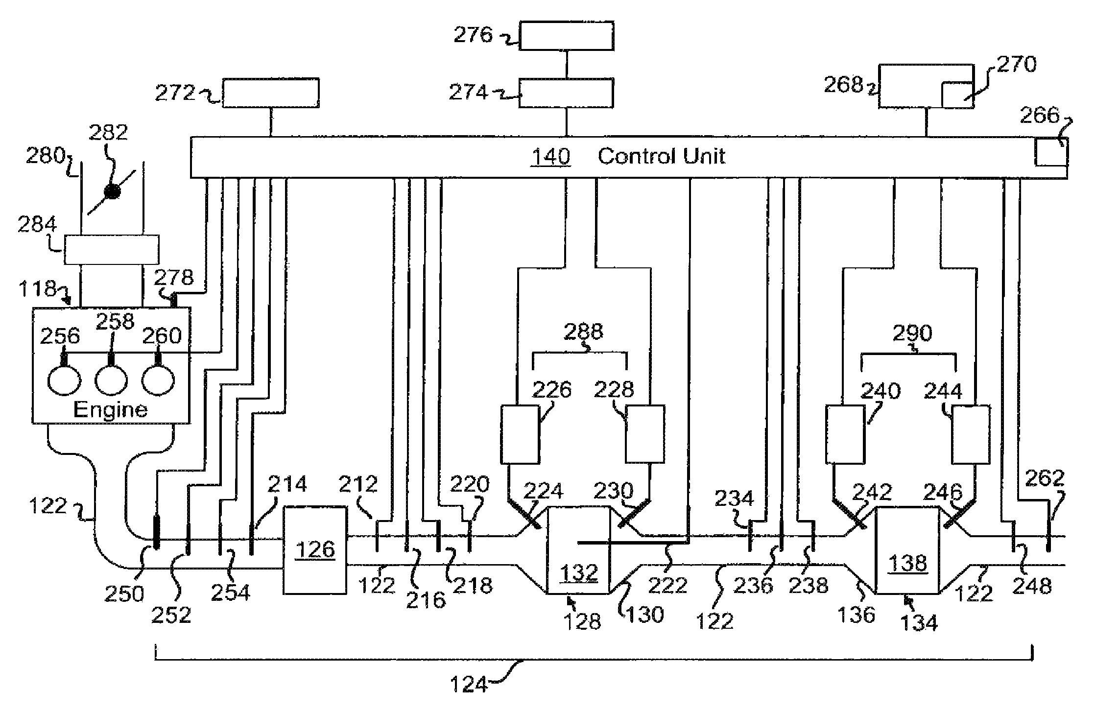
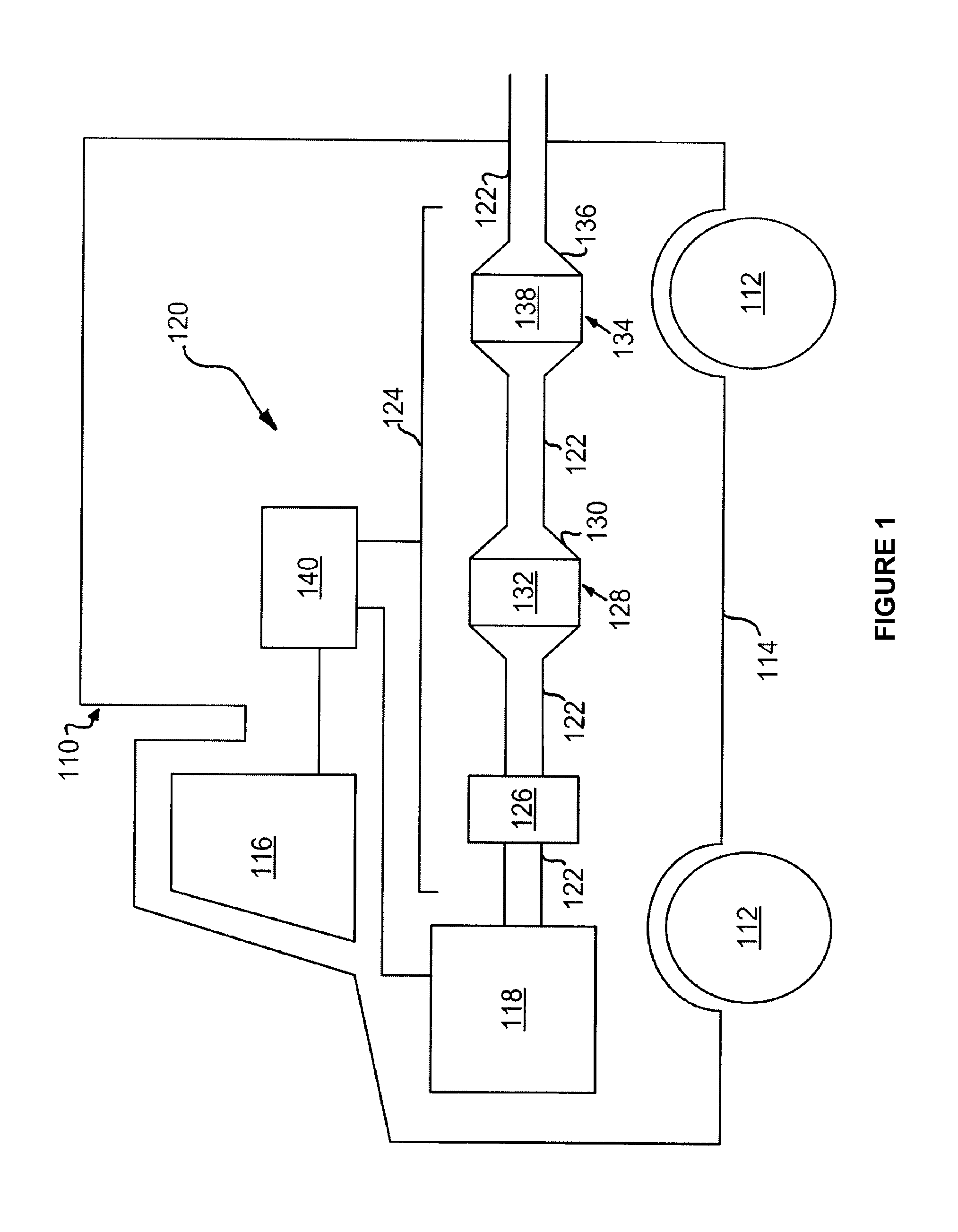
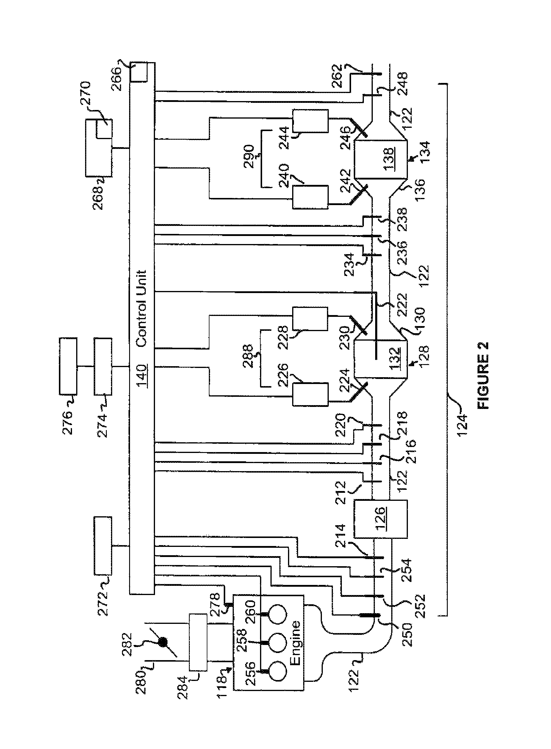
[0046]FIG. 1 depicts a machine 110. The machine 110 may include a traction device 112 such as wheels, belts, tracks, or other means for self-propulsion. Alternatively, the machine 110 may be stationary or mounted in a fixed location. The machine 110 may also include a frame 114, an operator station 116, an engine 118, a particulate filter control system 120, and an exhaust after-treatment system 124. The exhaust after-treatment system 124 may be connected to the engine 118, which may be mounted to the frame 114 of the machine 110.

[0047]The engine 118 may be any type of engine that produces a flow of exhaust gases. For example, engine 118 may be an internal or external combustion engine. Specifically, engine 118 may be a diesel engine, gasoline engine, an engine burning gaseous fuel, such as natural gas or hydrogen, or any other engine. Alternatively, engine 118 may be a turbine, combustor, or burner that also produces exhaust gases.

[0048]The exhaust after-treatment system 124 may be...


PUM

PropertyMeasurementUnit
Temperatureaaaaaaaaaa
Pressureaaaaaaaaaa
Flow rateaaaaaaaaaa

Abstract

A particulate filter control system and method for controlling the same is disclosed. The particulate filter load monitoring system may transmit radio frequency signals through the resonant cavity and filter medium across a frequency range sufficient to generate more than one resonant mode. The system may contain additional sensors for monitoring additional exhaust characteristics and parameters. Further, a control unit may be configured to determine the amount of material accumulated in the particulate filter, detect failures and malfunctions of the exhaust after-treatment system and its associated components, and initiate an action based on the amount of material accumulated in the particulate filter, the determination of a system failure or malfunction, or input from one or more exhaust sensors.

Description

[0001]This application is a continuation-in-part of U.S. patent application Ser. No. 11 / 741,832 filed Apr. 30, 2007, which claims the benefit of U.S. Provisional Patent Application 60 / 746,081, filed May 1, 2006, the disclosures of which are herein incorporated by reference in their entireties.[0002]This application claims priority to U.S. Provisional Patent Application Ser. No. 61 / 109,922, filed Oct. 31, 2008, the disclosure of which is herein incorporated by reference in its entirety.FIELD[0003]This application generally relates to a particulate filter control system and means for modifying system and engine operation, and specifically to a particulate filter control system having a particulate filter load monitoring system.BACKGROUND[0004]Particulate filters are used in a wide range of applications to reduce particulate matter emissions from engines and other combustion sources. Particulate matter or soot emissions consist of solid- or liquid-phase aerosol particles and may be com...

Claims


Application Information

Patent Timeline
IPC IPC(8): G01R27/32G01R27/04
CPCF01N3/025F01N3/035F01N3/106F01N9/002F01N13/009B01D46/444F01N2370/22F01N2560/05F01N2560/12F01N2560/14F01N2900/0422F01N2900/1606Y02T10/47F01N2560/06F01N9/00F01N11/00F01N3/021F01N3/023F01N2560/02F01N2900/14F01N2900/1611Y02T10/40B01D46/44
Inventor BROMBERG, LESLIESAPPOK, ALEXANDERKOERT, PETER
Owner FILTER SENSING TECH
Learn More