Eureka AIR delivers breakthrough ideas for toughest innovation challenges, trusted by R&D personnel around the world.

Real-time processor executing predetermined operation defined by program correctly at predetermined time

a real-time processor and predetermined time technology, applied in the field of microprocessors, can solve the problems of difficult to calculate the appropriate delay time during the creation of the program, the microprocessor is not suited for applications, and the period of time required for the microprocessor to execute the program is complex

Inactive Publication Date: 2006-06-27
SHARP KK
View PDF18 Cites 13 Cited by
  • Summary
  • Abstract
  • Description
  • Claims
  • Application Information

AI Technical Summary

Benefits of technology

The present invention provides a real-time processor that can carry out a predetermined operation at a predetermined time, regardless of various factors. It also provides a method for carrying out processing without overflow of the timer that measures the time. Additionally, it can detect and recover from failure of execution of a predetermined operation. The invention also includes an instruction execution method that can carry out a predetermined operation at a predetermined time. Overall, the invention ensures accurate and efficient execution of predetermined operations at specific times.

Problems solved by technology

However, the period of time required for the microprocessor to execute the program varies in a complex manner depending upon various factors such as the value of the processed data, the memory operation time (access delay), the frequency of the clock signal, and the like.
When the program becomes extremely complicated, it will become difficult to calculate the appropriate delay time during creation of the program.
This microprocessor is not suited for applications in which a certain instruction is repeatedly executed infinitely at a constant time interval.
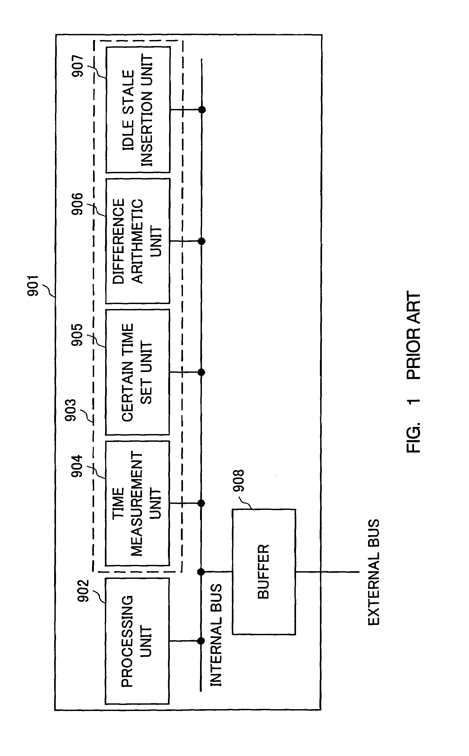
There was problem that this microprocessor could not carry out the recovery procedure in the case where the difference calculated by difference arithmetic unit 906 provides a negative value.

Method used


Image

  • Real-time processor executing predetermined operation defined by program correctly at predetermined time
  • Real-time processor executing predetermined operation defined by program correctly at predetermined time
  • Real-time processor executing predetermined operation defined by program correctly at predetermined time

Examples


first embodiment

[0086]FIG. 8 is a block diagram showing an example of a system using a real-time processor according to a first embodiment of the present invention. This system includes a real-time processor 1, a memory device 2 in which the program executed by real-time processor 1 and data are stored, and an input / output device 3 to provide data input / output with an external equipment. Real-time processor 1, memory device 2 and input / output device 3 are connected to a memory address bus (MAB) and a memory data bus (MDB). Real-time processor 1 generates a timing signal applied to input / output device 3 to control the same.

[0087]The method of real-time processor 1 controlling input / output device 3 includes the method of allocating a control register that controls input / output device 3 to a memory space, to an I / O (Input / Output) space, to a particular internal register, or the like. A system employing the method of allocating a control register to a memory space will be described hereinafter. However...

second embodiment

[0139]FIG. 17 is a block diagram showing a schematic structure of a real-time processor according to a second embodiment of the present invention. The real-time processor of the second embodiment differs from the real-time processor of the first embodiment shown in FIG. 9 in that an execution time register 21, a TF register 22 and a combination logic circuit 23 are additionally provided and the instruction processing unit further includes the feature of controlling these additional circuits. Detailed description of the same structure and function will not be repeated. In the second embodiment, the real-time processor is designated 1a and the instruction processing unit is designated 10a.

[0140]Execution time register 21 has the data input terminal connected to TRQ signal, the clock input terminal connected to ERCK signal, and the output terminal connected to ERQ signal. The value of TRQ is entered in execution time register 21 at the rising edge of ERCK signal to be output as ERQ si...

third embodiment

[0161]FIG. 25 is a block diagram showing a schematic structure of a real-time processor according to a third embodiment of the present invention. The real-time processor of the third embodiment differs from the real-time processor of the first embodiment shown in FIG. 9 in that a selector 30 selecting a value to be input to subtracter 15, a selector 31 selecting a value to be input to time register 12, and a subtracter 32 subtracting the value in clock register 11 from the value stored in time register 12 are additionally provided with the feature in the instruction processing unit to control these additional circuits. Therefore, detailed description of corresponding components and features will not be repeated. In the third embodiment, the real-time processor is designated 1b, and the instruction processing unit is designated 10b.

[0162]Selector 30 has one input terminal connected to MTRSD signal, the other input terminal connected to URQ signal, the select signal input terminal co...


PUM


Abstract

A real-time processor includes a clock register updating a time at a predetermined interval, a time register storing an arbitrary time, a time comparator comparing the time in the clock register with the time stored in the time register, and an instruction processing unit executing an instruction whose execution status is altered according to the comparison result of the time comparator. A predetermined operation can be carried out correctly at a predetermined time since the instruction processing unit executes an instruction whose execution status is altered according to the comparison result of the time comparator.

Description

BACKGROUND OF THE INVENTION[0001]1. Field of the Invention[0002]The present invention relates to a microprocessor that operates according to a program. Particularly, the present invention relates to a real-time processor that executes a predetermined operation defined by a program correctly at a predetermined time.[0003]2. Description of the Background Art[0004]In accordance with the development of microprocessor techniques, microprocessors are now beginning to be used also for the control of hardware which have been conventionally carried out by an application specific circuit. It is important to adjust the operation timing so that the microprocessor outputs an appropriate control signal at an appropriate time in order to control the hardware properly. This operation timing must not be earlier nor delayed than the predetermined time.[0005]For the adjustment of the operation timing by the microprocessor, the method of inserting a NOP (No Operation) instruction or empty loop in the p...

Claims


Application Information

Patent Timeline
Patent Type & Authority Patents(United States)
IPC IPC(8): G06F9/00G06F1/12G06F1/14G06F9/38G06F9/30G06F9/32G06F15/78
CPCG06F1/12G06F1/14G06F9/3857G06F9/322G06F9/3836G06F9/30079G06F9/3858G06F9/3854G06F9/323
Inventor TAKAHASHI, MASAFUMI
Owner SHARP KK
Why Eureka
Eureka Blog
Learn More