
Fuel cell separator

a fuel cell separator and separator technology, applied in the direction of basic electric elements, electrical equipment, materials and papermaking, etc., can solve the problems of unsuitable mass production methods, long composition time, and difficult heat resistance of the separator to hot water, so as to maintain the necessary strength properties, excellent heat resistance to hot water, and the effect of increasing the number o

Active Publication Date: 2013-02-12
NISSHINBO CHEM
View PDF16 Cites 0 Cited by
  • Summary
  • Abstract
  • Description
  • Claims
  • Application Information

AI Technical Summary

Benefits of technology

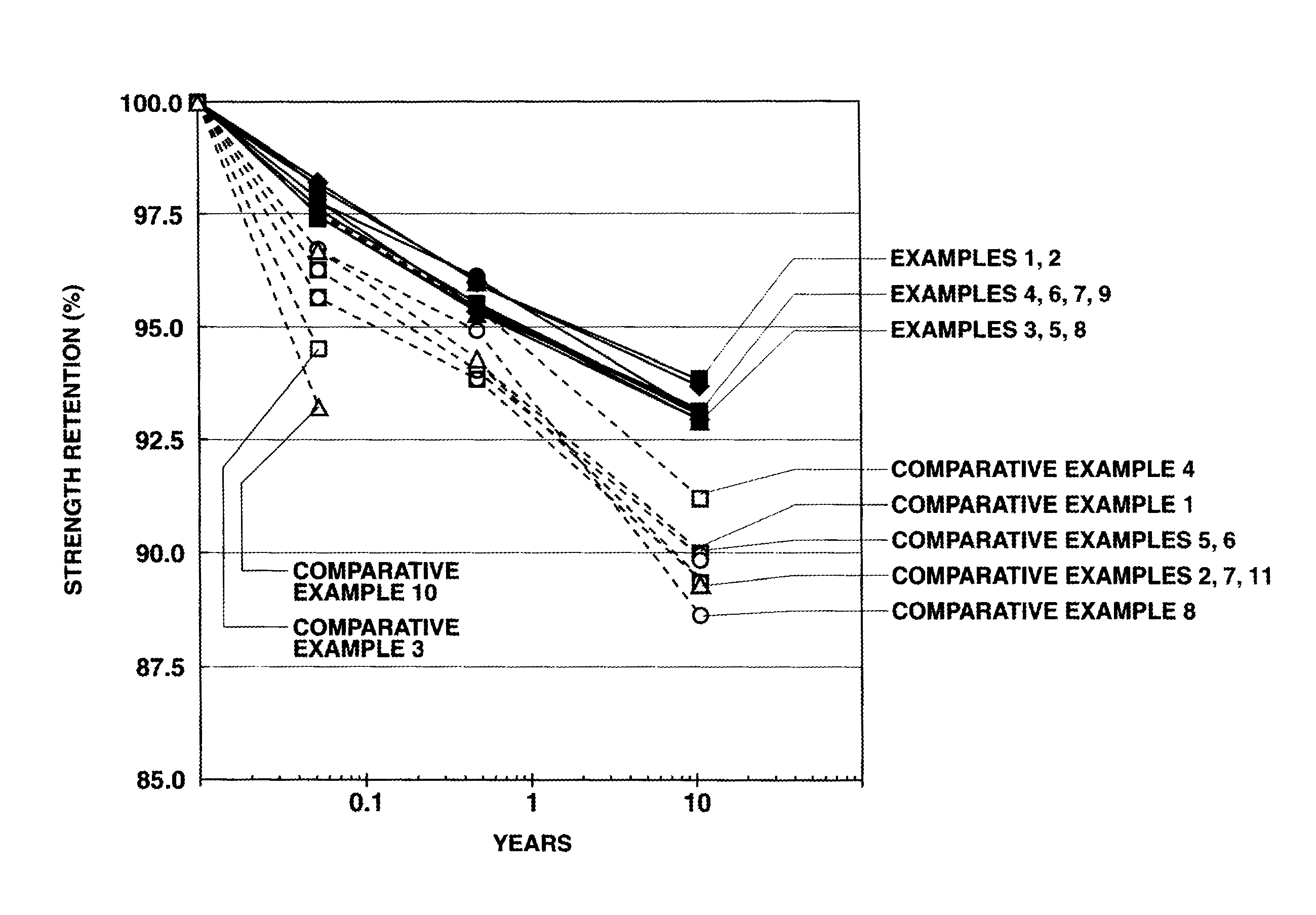
The solution provides a fuel cell separator with excellent resistance to heat and hot water, maintaining strength properties over an extended period, preventing damage and ensuring durability in harsh environments.

Problems solved by technology

However, in the methods of Patent Documents 1 and 2, because a resin having ester bonds is used in the fuel cell separator composition, hydrolysis may arise in the resin during power generation by the fuel cell, making the resistance of the fuel cell separator to hot water problematic.
Moreover, curing of the composition takes a long time, and so these methods are also unsuitable for mass production.
In the methods of Patent Documents 3 to 7, because an epoxy resin having a high content of hydrolyzable chlorine is used in the fuel cell separator composition, the hydrolyzable chlorine lowers the crosslink density of the cured product, as a result of which the resulting fuel cell separator has insufficient heat resistance.
In the method of Patent Document 8, when triphenylphosphine is used as the cure accelerator, the resulting fuel cell separator has insufficient heat resistance.
When 2-phenyl-4-methyl-5-hydroxymethylimidazole is used as the cure accelerator, owing to the poor compatibility between the accelerator and the epoxy resin, the curing reactions have difficulty proceeding, and so the resulting fuel cell separator has insufficient strength and heat resistance.
In the method of Patent Document 9, because triphenylphosphine is used as the cure accelerator, the resulting fuel cell separator has insufficient heat resistance.
When a fuel cell separator lacks adequate resistance to heat and hot water as in the case of the separators disclosed in each of the above patent documents, deformation and cracking sometimes arise during power generation within such an environment.

Method used


Image

  • Fuel cell separator
  • Fuel cell separator

Examples


example 1

[0074]One hundred parts by weight of flake graphite powder (average particle size: 30 μm at d50 in particle size distribution), a binder component resin composed of 18.3 parts by weight of o-cresol novolak epoxy resin (epoxy equivalent weight, 199 g / eq; ICI viscosity, 0.29 Pa·s; hydrolyzable chlorine concentration, 370 ppm), 9.6 parts by weight of novolak phenolic resin (hydroxyl equivalent weight, 103 g / eq; ICI viscosity, 0.22 Pa·s) and 0.19 part by weight of 2-phenylimidazole, and 0.5 part by weight of carnauba wax as the internal mold release agent were charged into a Henschel mixer and mixed together at 500 rpm for 3 minutes to prepare a fuel cell separator composition.

[0075]The resulting composition was charged into a 200 mm×200 mm mold for manufacturing a fuel cell separator and compression-molded at a mold temperature of 185·C and a molding pressure of 30 MPa for a molding time of 30 seconds, thereby giving a fuel cell separator.

example 2

[0076]Aside from replacing the o-cresol novolak epoxy resin used in Example 1 with 18.1 parts by weight of another o-cresol novolak epoxy resin (epoxy equivalent weight, 193 g / eq; ICI viscosity, 0.17 Pa·s; hydrolyzable chlorine concentration, 390 ppm) and setting the amount of novolak phenolic resin to 9.8 parts by weight, a fuel cell separator composition was prepared and compression-molded under the same conditions as in Example 1 to give a fuel cell separator.

example 3

[0077]Aside from replacing the o-cresol novolak epoxy resin used in Example 1 with 18.5 parts by weight of another o-cresol novolak epoxy resin (epoxy equivalent weight, 206 g / eq; ICI viscosity, 0.73 Pa·s; hydrolyzable chlorine concentration, 390 ppm) and setting the amount of novolak phenolic resin to 9.3 parts by weight, a fuel cell separator composition was prepared and compression-molded under the same conditions as in Example 1 to give a fuel cell separator.


PUM

PropertyMeasurementUnit
glass transition pointaaaaaaaaaa
ICI viscosityaaaaaaaaaa

Abstract

Provided is a fuel cell separator that has excellent resistance to heat and hot water and has a glass transition temperature between 140° C. and 165° C. Said fuel cell separator is formed by curing a composition containing a graphite material and a binder component resin. The binder component resin contains a cresol novolac epoxy resin having a hydrolysable chlorine content of at most 450 ppm and an epoxy equivalent weight of 192-210 g / eq, a phenol resin having a hydroxyl equivalent weight of 103-106 g / eq, and an imidazole compound having a molecular weight between 140 and 180.

Description

TECHNICAL FIELD[0001]The present invention relates to a fuel cell separator (bipolar plate), and more particularly to a fuel cell separator which has an excellent resistance to heat and hot water.BACKGROUND ART[0002]One role of the fuel cell separator is to confer each unit cell with electrical conductivity. In addition, separators provide flow channels for the supply of fuel and air (oxygen) to the unit cells and also serve as boundary walls separating the unit cells. Characteristics required of a separator thus include a high electrical conductivity, a high impermeability to gases, chemical stability and heat resistance. In household fuel cell applications in particular, long-term chemical stability is required.[0003]Techniques for achieving these characteristics include the methods disclosed in Patent Documents 1 to 9.[0004]However, in the methods of Patent Documents 1 and 2, because a resin having ester bonds is used in the fuel cell separator composition, hydrolysis may arise i...

Claims


Application Information

Patent Timeline
Patent Type & Authority Patents(United States)
IPC IPC(8): B28B7/36C04B28/36D21H21/16C09J11/06
CPCH01M8/0213H01M8/0221H01M8/0226C08G59/4042C08G59/621C08L63/00C08G59/08H01M2008/1095Y02E60/50C08K3/04
Inventor TANNO, FUMIO
Owner NISSHINBO CHEM
Learn More