Compensation circuit for current peaking reduction in notification appliances

a technology of compensation circuit and notification appliance, which is applied in the direction of lighting apparatus, instruments, light sources, etc., can solve the problems of shortened turn-on time, increased risk of epileptic seizures, and increased risk of seizures, so as to achieve long cycle time

Active Publication Date: 2013-01-15
JOHNSON CONTROLS TYCO IP HLDG LLP
View PDF5 Cites 3 Cited by
  • Summary
  • Abstract
  • Description
  • Claims
  • Application Information

AI Technical Summary

Benefits of technology

[0012]Various embodiments may also be directed to a notification appliance comprising one or more optical elements, an optical element driving circuit and a current peaking circuit. In some embodiments, the optical element driving circuit may be configured to drive the one or more optical elements. The current peaking circuit may be configured to reduce the start-up frequency of a pulse-width modulated signal during a first time period to enable a substantially long cycle time to reset inductor flux by extending the dead-time in a constant current operation of the notification appliance in various embodiments.

Problems solved by technology

Strobes in the same viewing area typically must be synchronized, as a fast flash rate or several unsynchronized strobes at the normal rate could cause susceptible people to have epileptic seizures.
This may be because current peaking may culminate in the addition of unwanted surge current when a number of notification appliances are populated and synchronized.
Despite these efforts, significant current peaking may still occur early and unintentionally in the notification appliance circuits in its steady-state operation.
Although current peaking in these circuits may lead to shorter turn-on times for the notification appliances, the remnant charge for each duty cycle must be discharged before the next PWM cycle occurs.
However, this application may not be suitable for flash tube constant-current PWM regulators that only regulate current.
As a result, any form of compensation may not only distort input current waveforms and remove regulator control, but may also affect the net amount of energy delivered to a discharge (load) capacitor on a cycle-per-cycle basis.
Even when a PWM is well designed and toleranced for a given application where the duty cycle variation is high, there is still a possibility that with narrow dead-time (e.g., substantially no inductor cycling turn-on or turn-off) the magnetic remanence may maintain a residual flux that may end-up causing peak currents.
For example, in the initial phases where the (tcycle=tturn-on+tturn-off) time is very high, dead time may become very minimal which may result in a build-up of magnetic flux that does not get fully discharged.
This build up may affect efficiency and may also draw extra current that does not translate into extra output.

Method used


Image

  • Compensation circuit for current peaking reduction in notification appliances
  • Compensation circuit for current peaking reduction in notification appliances
  • Compensation circuit for current peaking reduction in notification appliances

Examples


Embodiment Construction

[0020]The present disclosure will now be described more fully hereinafter with reference to the accompanying drawings, in which preferred embodiments of the invention are shown. This invention, however, may be embodied in many different forms and should not be construed as limited to the embodiments set forth herein. Rather, these embodiments are provided so that this disclosure will be thorough and complete, and will fully convey the scope of the invention to those skilled in the art. In the drawings, like numbers refer to like elements throughout.

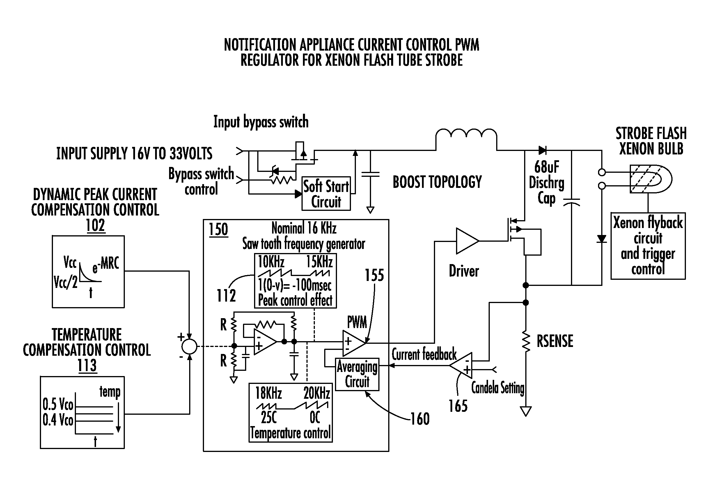
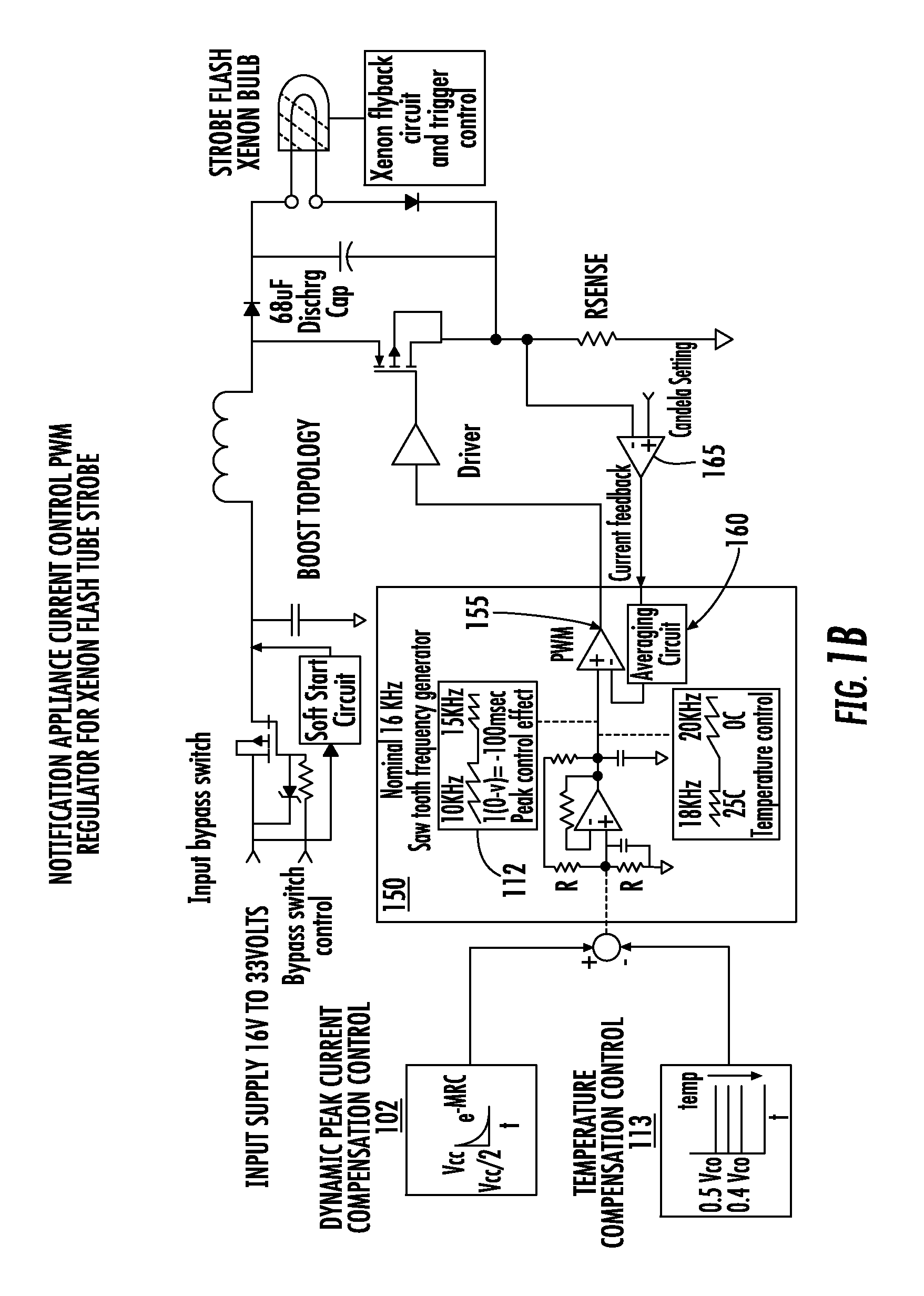
[0021]Various embodiments may be generally directed to reducing current peaking in notification appliances. In one embodiment, for example, a current peaking compensation circuit may comprise two or more transistors and one or more capacitors configured to reduce a start-up frequency of a pulse-width modulated signal during a first time period and to add a time constant decaying voltage across a resistor divider network to increase a refe...


PUM


Abstract

A system and apparatus to reduce current peaking in notification appliances are described. The apparatus may include a current peaking compensation circuit comprising two or more transistors and one or more capacitors configured to reduce a start-up frequency of a pulse-width modulated signal during a first time period and to add a time constant decaying voltage across a resistor divider network to increase a reference voltage during the first time period. Other embodiments are described and claimed.

Description

FIELD OF THE INVENTION[0001]Embodiments of the present disclosure relate to compensation circuits for current peaking reduction. More particularly, the present disclosure relates to compensation circuits for reducing current peaking in current controlled pulse-width modulation (PWM) circuits for notification appliances such as those used in fire alarm systems.DISCUSSION OF RELATED ART[0002]Visual notification appliances, e.g. warning lights, are often used within buildings in conjunction with audio warning alarms so that the hearing impaired can be alerted to emergency conditions such as a fire. Typically, the visual notification appliance includes a flashing bulb or strobe positioned within a reflector. The bulb receives power from a power supply in a control panel. This power supply is normally powered by the building's AC supply, but also provides battery backup to ensure that the visual notification appliance will have power in the event power to the building is disrupted.[0003]...

Claims


Application Information

Patent Timeline
Patent Type & Authority Patents(United States)
IPC IPC(8): H05B37/02
CPCH05B41/28H05B41/34H05B37/02H05B47/10
Inventor REDJEBIAN, BERJ
Owner JOHNSON CONTROLS TYCO IP HLDG LLP
Why Eureka
Try Eureka