Arrangement and method for monitoring a power supply

Active Publication Date: 2016-07-21
SIEMENS AG
View PDF2 Cites 6 Cited by
  • Summary
  • Abstract
  • Description
  • Claims
  • Application Information

AI Technical Summary

Benefits of technology

[0010]It is an object of the invention to provide an improved arrangement and method for monitoring a power supply.

Problems solved by technology

As soon as the power supply fails or the signal line is interrupted, the high signal inevitably switches over to a low signal.

Method used


Image

  • Arrangement and method for monitoring a power supply
  • Arrangement and method for monitoring a power supply
  • Arrangement and method for monitoring a power supply

Examples


Embodiment Construction

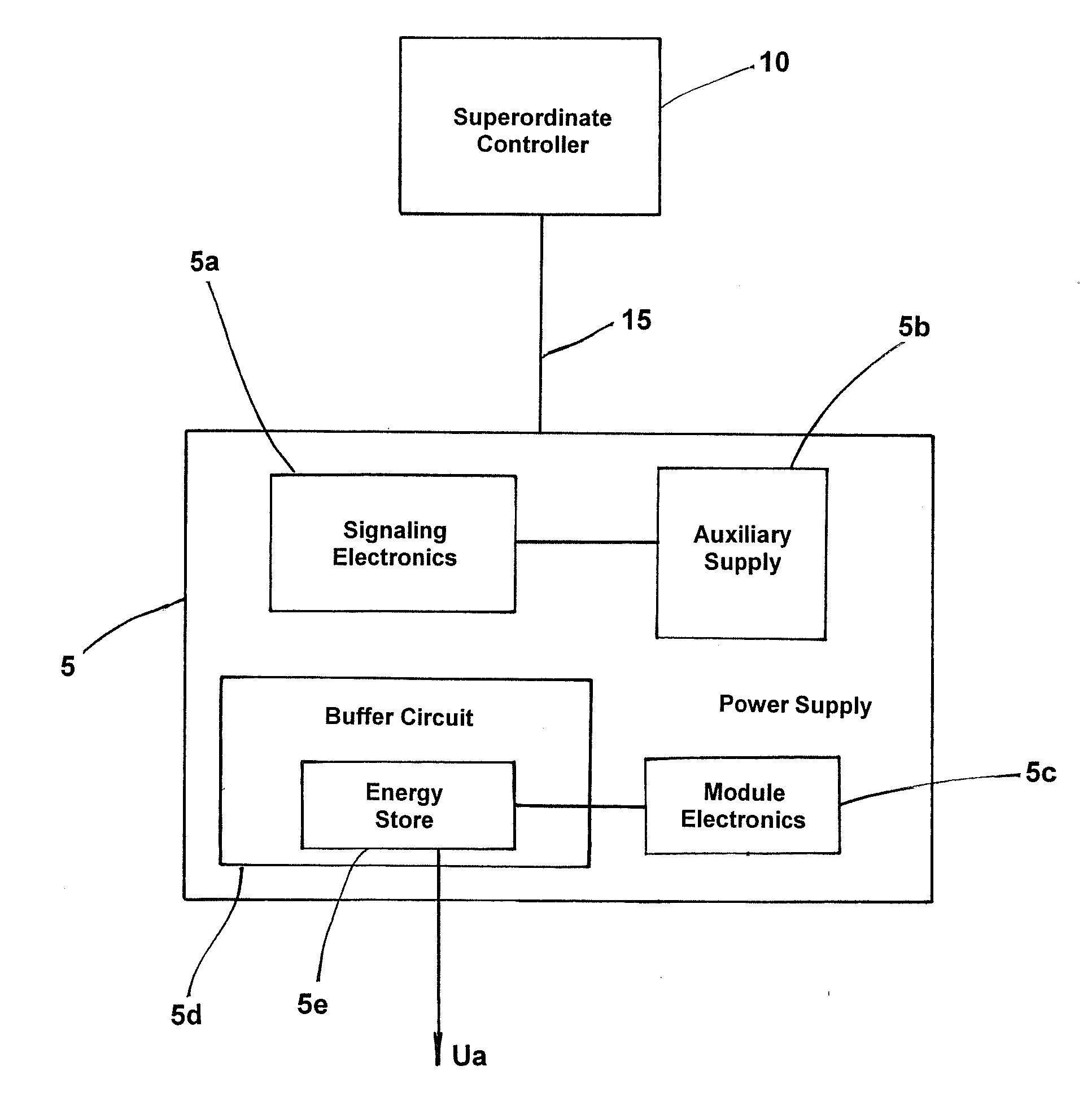
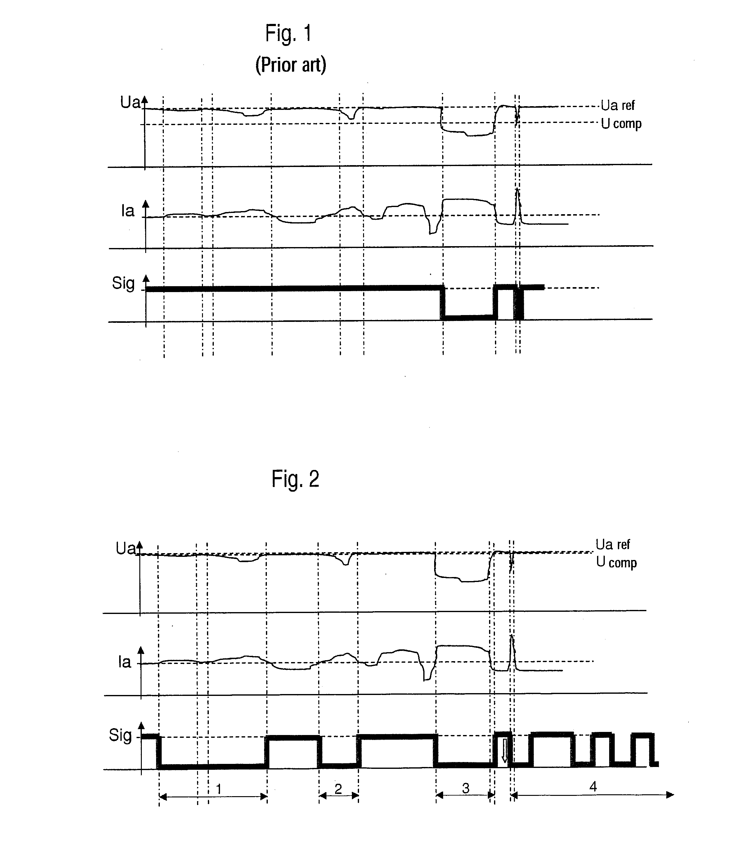
[0040]Conventional power supplies signal dips in output voltage via an indicating signal Sig, which is derived directly from the measured output voltage Ua (see FIG. 1). For as long as the output voltage Ua corresponds to a reference voltage Ua ref, a high signal is transmitted to a superordinate controller. If, however, the output voltage Ua falls below a threshold value U comp, then the indicating signal Sig is switched over to a low signal. A current limiter causes the output voltage Ua to fall if the output current Ia exceeds a current limit.

[0041]If such an indicating signal switches into the low state for only a few milliseconds, the detection is dependent on the query behavior of the superordinate controller. If the superordinate controller involves a stored program controller with a variable cycle time, the input at which the indicating signal is present is queried, generally only once per execution of the cycle. It is then left to chance whether there is a query during a br...


PUM


Abstract

A method for monitoring a power supply connected to a superordinate controller via a signal line, wherein the superordinate controller queries whether the power supply is operating faultlessly at variable intervals, where during faultless operation, a power-good signal is continuously transmitted by the power supply to the superordinate controller via the signal line and, if a fault occurs, an indicating signal is transmitted by the power supply to the superordinate controller via the signal line as a switching sequence of high and low signals such that each signal change of the switching sequence occurs only after a time period that is longer than an expected greatest query interval and each signal of the switching sequence that does not correspond to the power-good signal is shorter than a specified signal duration for indicating a total failure of the power supply, whereby the superordinate controller receives more information than previously.

Description

CROSS-REFERENCE TO RELATED APPLICATIONS[0001]This is a U.S. national stage of application No. PCT / EP2014 / 068607 filed 2 Sep. 2014. Priority is claimed on European Application No. 13182998 filed 4 Feb. 2013, the content of which is incorporated herein by reference in its entirety.BACKGROUND OF THE INVENTION[0002]1. Field of the Invention[0003]The invention relates to an arrangement and method for monitoring a power supply which is connected to a superordinate controller by means of via a signal line, where the superordinate controller is used to query whether the power supply is operating faultlessly at variable query intervals.[0004]2. Description of the Related Art[0005]In various arrangements that include power supplies, the need arises to check the status of the power supply and to detect the occurrence of a fault via a superordinate controller. This is especially the case with industrial plants, where a number of power supplies are connected via signal lines to a central plant c...

Claims


Application Information

Patent Timeline
Patent Type & Authority Applications(United States)
IPC IPC(8): G01R31/40
CPCG01R31/40H03K5/125H02H1/0076G06F1/28G06F1/26
Inventor SCHWEIGERT, HARALD
Owner SIEMENS AG
Why Eureka
Try Eureka