Two-stroke internal combustion engine

a two-stroke, internal combustion engine technology, applied in combustion engines, cylinders, pipes, etc., can solve the problems of reducing affecting the combustion efficiency of the engine, and the cylinders are difficult to mold, so as to improve the combustion efficiency, and reduce the passage sectional area

Active Publication Date: 2013-01-15
YAMABIKO CORP
View PDF16 Cites 4 Cited by
  • Summary
  • Abstract
  • Description
  • Claims
  • Application Information

AI Technical Summary

Benefits of technology

[0014]However, with the hitherto proposed techniques, it cannot be said that emission regulations and demands for improved fuel economy, which are bound to become even more stringent in the years to come, can be addressed to a sufficient extent, and the situation is such that there are strong demands for a new technique that is capable of suppressing the short-circuiting of fresh charge more than has been possible, while at the same time being capable of further improving scavenging efficiency, combustion efficiency, etc.
[0015]The present invention has been made in order to address such demands, and an object thereof is to provide a reverse scavenged two-stroke internal combustion engine that is capable of effectively suppressing the short-circuiting of fresh charge, while at the same time being capable of further improving scavenging efficiency, combustion efficiency, etc.
[0025]With a reverse scavenged two-stroke internal combustion engine according to the present invention, because the horizontal sectional shape of the scavenging passages is closer to a triangle than a parallelogram (i.e., the conventional horizontal sectional shape) along substantially the entire lengths of the scavenging passages, where the cylinder outer circumferential side of the horizontal sectional shape is narrowest and the cylinder bore wall surface side of the horizontal sectional shape is wide, by way of the effects of this shape and of reducing the passage sectional area, the scavenging flow speed through the scavenging passages is increased, scavenging efficiency improves and, further, the scavenging flow speed into the combustion actuating chamber is also increased, and more air-fuel mixture is supplied, thereby making it possible to improve output, fuel economy, etc. In addition, as the scavenging flow speed into the combustion actuating chamber increases, flame propagation speed increases, thereby allowing for an improvement in combustion efficiency.
[0026]In addition, because the horizontal scavenging angles, which are the angles of intersection formed between the lines extended towards the intake port from the guide wall surfaces that define the scavenging passages, are made to be acute and, in a preferred embodiment, the lines extended from at least one pair of the scavenging passages fall outside of a tangent line that passes through an end point of the scavenging outlet of the scavenging passages that is closest to the intake port, it is possible to impart directionality to the air-fuel mixture blown out from the scavenging outlet towards the intake port of the combustion actuating chamber, thereby making it possible to suppress the short-circuiting of fresh charge. For this reason, in combination with the above-mentioned effects of the shape and of reducing the passage sectional area, there are considerable improvements in scavenging efficiency and combustion efficiency, making it possible to dramatically reduce THC, while at the same time making it possible to further improve output and fuel economy.
[0027]Further, with a reverse scavenged two-stroke internal combustion engine of this kind, for purposes of convenience in molding the cylinder and the crankcase, the lower ends of the scavenging passages are ordinarily made to open to the main bearing receiving face of the upper crankcase. In other words, when the lower ends of the scavenging passages are closed, they become undercut portions, making molding difficult. In the present invention, the sectional shape of the scavenging passages is made to be a triangle-like shape as mentioned above, and the passage sectional area is made considerably smaller than its conventional counterpart (approximately 60% of the conventional example in the embodiments of the present invention), as a result of which the opening area of the main bearing receiving face is made considerably smaller than is conventional. Consequently, the area of the main bearing receiving face subjected to pressure can be made larger than its conventional counterpart, as a result of which support for the crankshaft stabilizes, and it is possible to suppress torque variation and the like as much as possible. In addition, since stiffness increases, deformation by heat is suppressed, and seizure resistance improves.

Problems solved by technology

For this reason, an unburnt air-fuel mixture often becomes mixed in the combustion waste gas (exhaust gas), the amount of fresh charge (unburnt air-fuel mixture) that is exhausted into the atmosphere without being used for combustion, that is, the so-called short circuited amount, is large, and fuel economy is inferior as compared to four-stroke engines.
Therefore, while the machines may be small in size, environmental pollution still is a concern, and there are such issues as how to accommodate emission regulations as well as demands for improved fuel economy, which are bound to become even more stringent in the years to come.
However, with the hitherto proposed techniques, it cannot be said that emission regulations and demands for improved fuel economy, which are bound to become even more stringent in the years to come, can be addressed to a sufficient extent, and the situation is such that there are strong demands for a new technique that is capable of suppressing the short-circuiting of fresh charge more than has been possible, while at the same time being capable of further improving scavenging efficiency, combustion efficiency, etc.
In other words, when the lower ends of the scavenging passages are closed, they become undercut portions, making molding difficult.

Method used


Image

  • Two-stroke internal combustion engine
  • Two-stroke internal combustion engine
  • Two-stroke internal combustion engine

Examples


Embodiment Construction

[0050]Embodiments of the present invention (first and second embodiments) are described below with reference to the drawings.

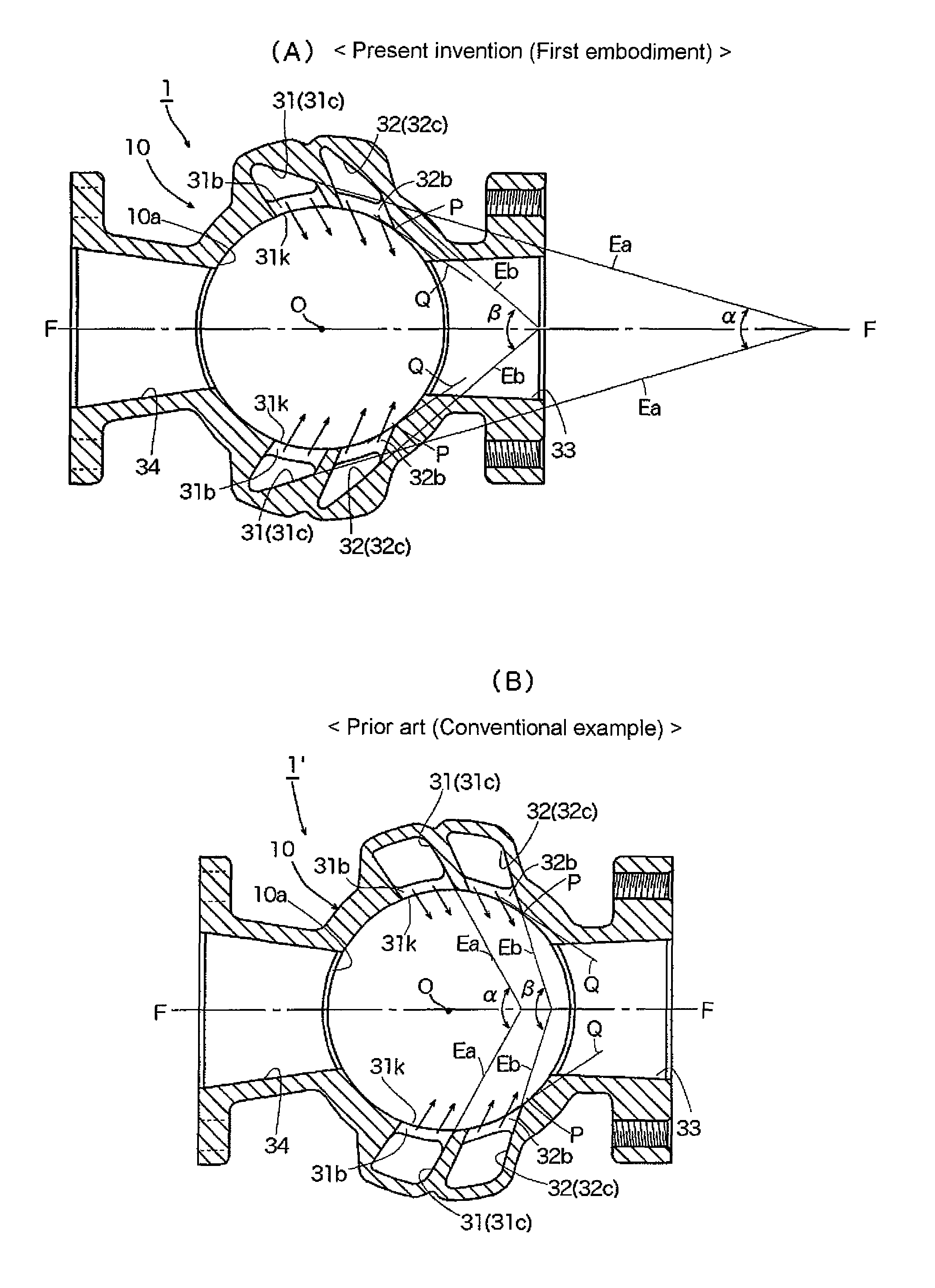
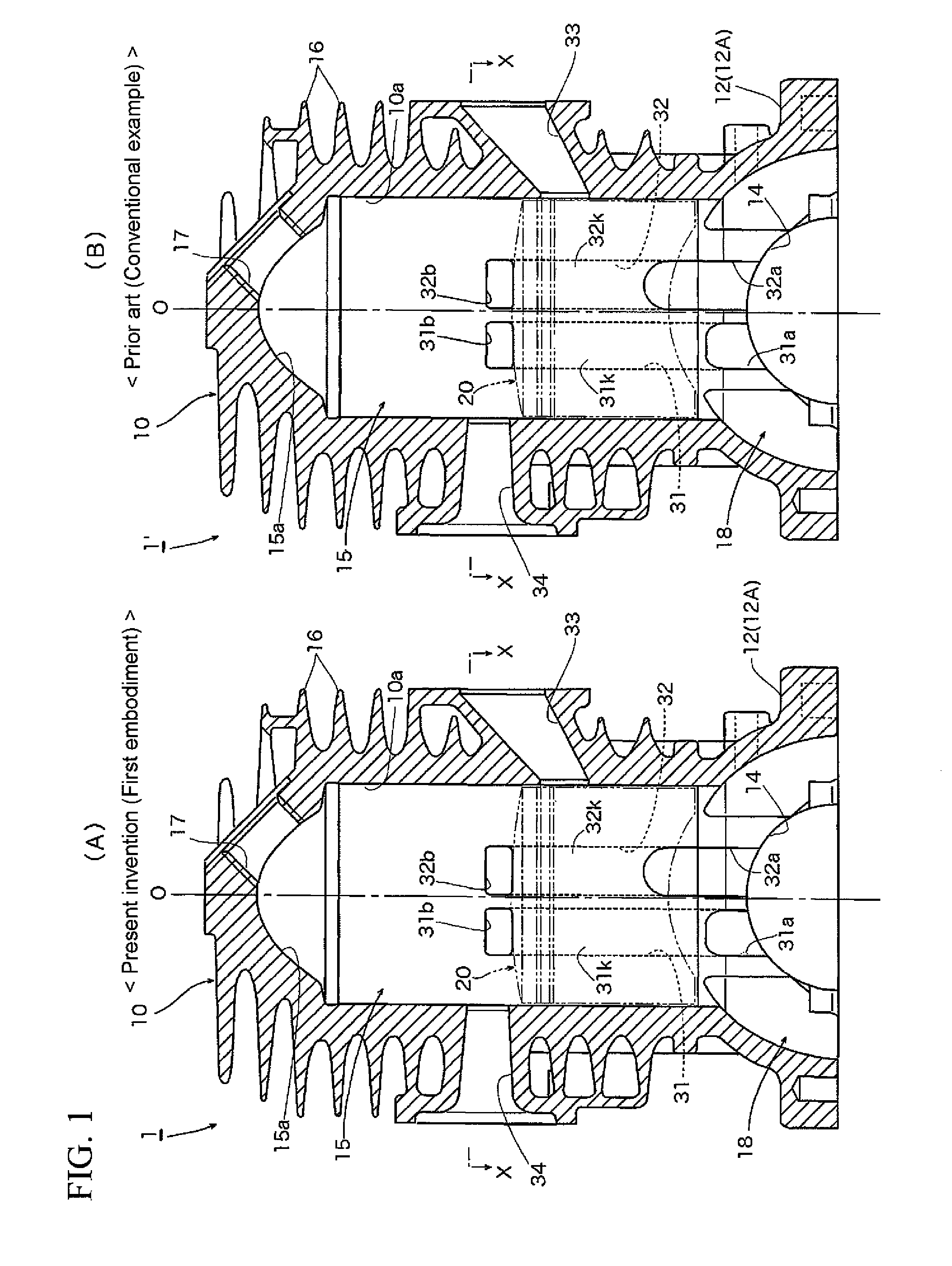
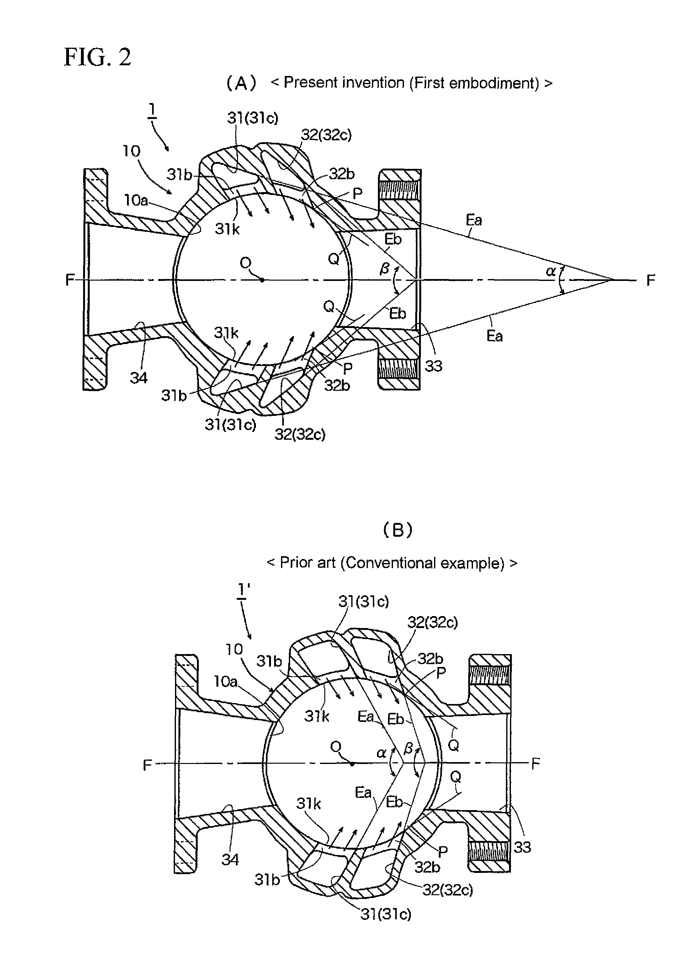
[0051]FIG. 1(A) is a vertical sectional view of an embodiment (first embodiment) of a reverse scavenged two-stroke internal combustion engine according to the present invention, and FIG. 1(B) is a vertical sectional view of a conventional example of a reverse scavenged two-stroke internal combustion engine. FIG. 2(A) is a sectional view taken along and as viewed in the direction of arrows X-X in FIG. 1(A), and FIG. 2(B) is a sectional view taken along and as viewed in the direction of arrows X-X in FIG. 1(B). FIG. 3(A) is a base view of the main portion of the engine shown in FIG. 1(A), and FIG. 3(B) is a base view of the main portion of the engine shown in FIG. 1(B). Line O-O in FIGS. 1(A) and 1(B) illustrates the axis of cylinder 10, defined through the center O of cylinder 10 illustrated in FIGS. 2(A)-2(B) and 3(A)-3(B). With respect to the engines of the f...


PUM


Abstract

A reverse scavenged two-stroke internal combustion engine is capable of effectively suppressing the short-circuiting of fresh charge (unburnt air-fuel mixture), while at the same time being capable of further improving scavenging efficiency, combustion efficiency, etc. The horizontal sectional shape of at least one pair of scavenging passages is closer to a triangle than a parallelogram along substantially the entire lengths of the at least one pair of scavenging passages, where a cylinder outer circumferential side of the horizontal sectional shape is narrowest and a cylinder bore wall surface side of the horizontal sectional shape is wide. Further, horizontal scavenging angles, which are angles of intersection formed between lines extended towards an intake port from guide wall surfaces that define the scavenging passages, are acute.

Description

BACKGROUND INFORMATION[0001]1. Field of the Invention[0002]The present invention relates to two-stroke internal combustion engines comprising one pair or a plurality of pairs of scavenging passages that adopt a reverse scavenging system, and more specifically to two-stroke internal combustion engines that are capable of suppressing the short-circuiting of fresh charge (unburnt air-fuel mixture), while at the same time also being capable of improving scavenging efficiency, combustion efficiency, and the like.[0003]2. Background Art[0004]Ordinarily, in standard two-stroke gasoline engines conventionally used in portable powered work machines, such as lawn mowers, chainsaws, etc., a spark plug is disposed at a head portion of a cylinder. An intake port, a scavenging port, and an exhaust port that are opened / closed by a piston are formed in a barrel portion of the cylinder. There are no independent strokes dedicated to intake and exhaust alone. And one cycle of the engine is completed w...

Claims


Application Information

Patent Timeline
Patent Type & Authority Patents(United States)
IPC IPC(8): F02B23/00F02B25/14F02B25/16F02B75/16
CPCF02B25/14F02B33/44F02B33/04F02B2075/025
Inventor KOGA, NAOKIYAMAGUCHI, SHIROUSHIRAI, KENYAMADA, DAISUKE
Owner YAMABIKO CORP
Why Eureka
Try Eureka