Outboard motor

a technology for outboard motors and motors, which is applied in the field of outboard motors, can solve the problems of increasing the temperature of the intake air of the engine, the low efficiency of the air to be suctioned into the engine, and the output of the engine, so as to reduce the temperature of the intake air of the engine, the effect of efficient cooling

Inactive Publication Date: 2012-12-25
YAMAHA MOTOR CO LTD
View PDF9 Cites 1 Cited by
  • Summary
  • Abstract
  • Description
  • Claims
  • Application Information

AI Technical Summary

Benefits of technology

[0007]More specifically, in the above-described outboard motor, the outer walls of the engine and components around the engine are cooled by air. However, the engine suctions air at a temperature which has increased. Therefore, a problem occurs in which a filling efficiency of the air to be suctioned into the engine becomes low and the output of the engine lowers. Further, the intake air temperature increases, and therefore, knocking easily occurs.
[0010]If the ignition timing of the engine is delayed to suppress an occurrence of knocking, the torque of the engine lowers, and the temperature of exhaust gas increases. When the exhaust system includes a catalyst, the temperature of the catalyst may excessively increase along with the increase in exhaust gas temperature.
[0017]On the other hand, a portion of the air inside the upper chamber is sent into the lower chamber by the fan. The air sent into the lower chamber is kept at a temperature equivalent to the temperature of the atmosphere. Also, the air sent into the lower chamber flows around the engine toward the air outlet. Accordingly, the engine and heating components such as electronic components provided in the lower chamber are efficiently cooled by the air.
[0018]Inside the upper chamber, water may enter from the air inlet. The fan sends water in the form of mist floating inside the upper chamber out of water, into the lower chamber together with air. Therefore, a portion of water which entered the upper chamber can be discharged downward by the fan. Therefore, water to be suctioned by the intake device can be reduced.
[0019]Thus, in the present preferred embodiment of the present invention, the temperature of intake air of the engine can be lowered. Further, components accommodated in the lower chamber such as the engine can be efficiently cooled. Further, water to be suctioned by the intake device can be reduced. Therefore, an outboard motor which can lower the intake air temperature, cool the engine, and reduce an amount of water to be suctioned by the intake device can be provided.

Problems solved by technology

Therefore, a problem occurs in which a filling efficiency of the air to be suctioned into the engine becomes low and the output of the engine lowers.
Further, the intake air temperature increases, and therefore, knocking easily occurs.
If knocking occurs frequently, a shock wave occurring inside the combustion chamber along with knocking breaks films of gas (boundary layers) on the surfaces inside the cylinder.
When the metal surfaces are melted, this finally results in breakage of the engine.

Method used


Image

  • Outboard motor
  • Outboard motor
  • Outboard motor

Examples


Embodiment Construction

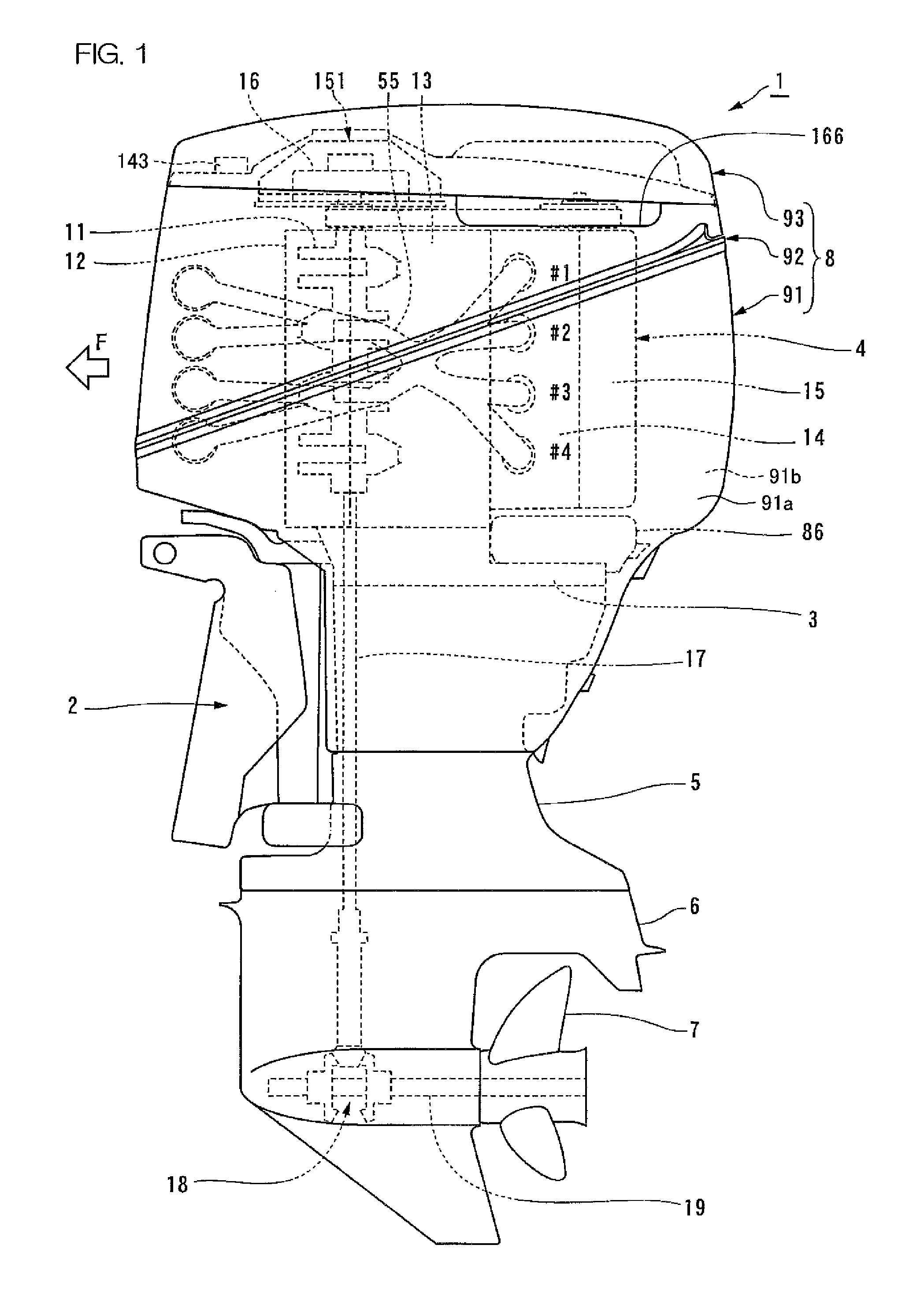
[0059]Hereinafter, an outboard motor 1 according to preferred embodiments of the present invention will be described in detail with reference to FIG. 1 to FIG. 28.

[0060]The outboard motor 1 as shown in FIG. 1 is to be attached to a transom board of a hull (not shown) so as to be steered and tilted via a bracket 2. Therefore, the outboard motor 1 can be in various postures with respect to the hull in an actual use state; however, in this specification, for the sake of convenience, based on a predetermined reference posture of the outboard motor 1, up-down, left-right, and front-rear directions are defined. The reference posture is a posture of the outboard motor 1 at a steering angle of zero and a tilt angle of zero with respect to the hull in the horizontal posture. In this condition, when a propulsive force in the forward drive direction is generated from the outboard motor 1, the hull moves straight ahead. In other words, in this specification, as expressions of directions of the ...


PUM


Abstract

An outboard motor includes an engine, an engine cover, a partitioning member, an intake device, and a fan. The engine is arranged to support a crankshaft extending along an up-down direction. The partitioning member is arranged to partition the inside of the engine cover into a lower chamber accommodating the engine and an upper chamber. In the partitioning member, a communication hole which is arranged to cause the upper chamber to communicate with the lower chamber is provided. Also, the engine cover has an air inlet arranged to cause the upper chamber to communicate with the atmosphere, and an air outlet arranged to cause the lower chamber to communicate with the atmosphere. The air inlet is arranged in an upper portion of the engine cover. The air outlet is arranged at a lower end portion of the engine cover. The intake device is connected to the engine. The intake device has an air suction port arranged to communicate with the upper chamber. The fan is arranged inside the engine cover. The fan is arranged to send air inside the upper chamber into the lower chamber through the communication hole.

Description

BACKGROUND OF THE INVENTION[0001]1. Field of the Invention[0002]The present invention relates to an outboard motor including an engine cover arranged to cover an engine.[0003]2. Description of Related Art[0004]An outboard motor according to a prior art is described in U.S. Pat. No. 5,806,311. This outboard motor includes an engine which is arranged to support a crankshaft extending along an up-down direction, and an engine cover covering the engine. Also, the outboard motor is arranged to prevent water which entered the inside of the engine cover from being suctioned into the engine together with air. In detail, the outboard motor is arranged to separate water from air by using a narrow space between the engine cover and the engine.[0005]In the space between the engine cover and the engine, an air passage in which intake air flows is provided. This air passage is arranged like a maze by outer walls of the engine and members such as an auxiliary machine installed in the outboard moto...

Claims


Application Information

Patent Timeline
Patent Type & Authority Patents(United States)
IPC IPC(8): F02B77/04
CPCB63H20/32F02B27/02F02B61/045F02M35/10039F02M35/10216F02M35/10301F02M35/168F02B2063/045Y02T10/146F02B27/0215F02B27/0231Y02T10/12
Inventor KONAKAWA, TSUGUNORITAKAHASHI, YUSUKE
Owner YAMAHA MOTOR CO LTD
Why Eureka
Try Eureka