
Three-way catalyst having an upstream multi-layer catalyst

a three-way catalyst and upstream technology, applied in the field of layered catalysts, can solve the problems of increased thermal degradation, increased loss, and loss of support surface area or pore volume, and achieve the effect of reducing the cost of pgm, and improving the efficiency of pgm

Active Publication Date: 2012-12-04
UMICORE AG & CO KG
View PDF6 Cites 42 Cited by
  • Summary
  • Abstract
  • Description
  • Claims
  • Application Information

AI Technical Summary

Benefits of technology

This configuration enhances the catalyst's performance by maintaining activity and reducing thermal degradation, achieving efficient emission control with reduced PGM loading, as demonstrated by improved THC and NOx performance after thermal aging.

Problems solved by technology

A disadvantage of locating catalysts close to the manifold is increased thermal degradation, and more rapid loss of activity, especially under high load / high speed conditions which results in loss of support surface area or pore volume and rapid sintering of the PGM.

Method used


Image

  • Three-way catalyst having an upstream multi-layer catalyst
  • Three-way catalyst having an upstream multi-layer catalyst
  • Three-way catalyst having an upstream multi-layer catalyst

Examples


examples

[0085]This invention will be illustrated by the following examples and descriptions. The following examples are intended to illustrate but not to limit the invention.

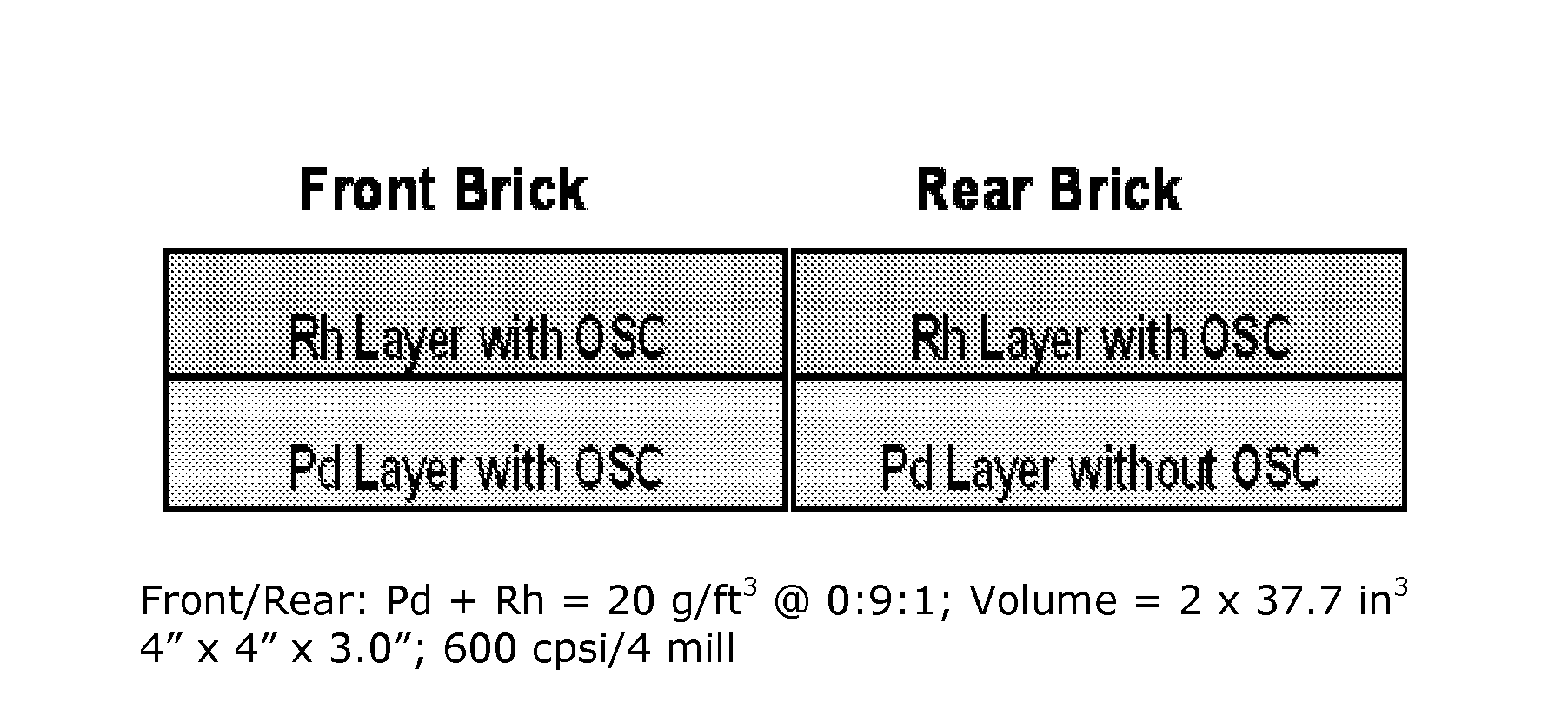
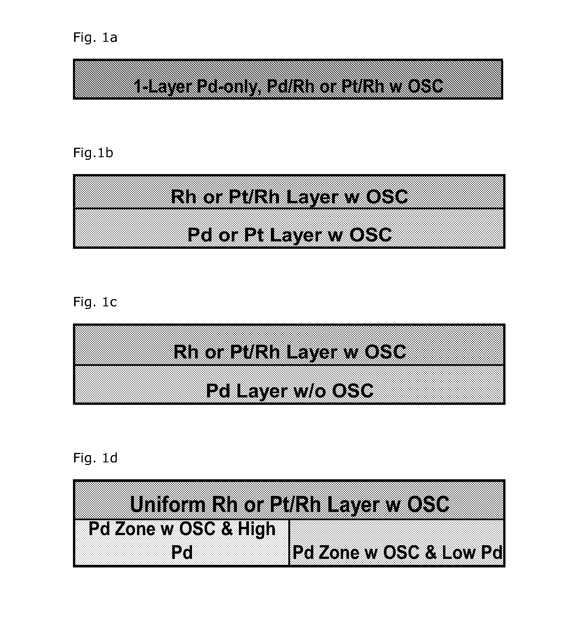
[0086]The WC composition configurations for a conventional reference catalyst (FIG. 4a) and a catalyst according to the present invention (FIG. 4b) were manufactured and compared as follows.

[0087]Manufacture of the 1st Catalytic Layer of the Convention Reference Catalyst (4a):

[0088]Preparation of the washcoats and coating has previously been described in U.S. Pat. No. 7,041,622, Column 9, Lines 20-40; Column 10, lines 1-15, which is herein incorporated by reference in its entirety. Alumina stabilized with 4% by weight of lanthanum oxide, barium sulfate and a mixed oxide oxygen storage material with a composition of 42% ZrO2+HfO2, 43% CeO2, 5% Pr6O11 and 10% La2O3 by weight were used in the preparation of the slurry. In making the layered catalysts, a slurry was prepared by first adding nitric acid to water at 1 wt % bas...


PUM

PropertyMeasurementUnit
operating temperaturesaaaaaaaaaa
distanceaaaaaaaaaa
temperaturesaaaaaaaaaa

Abstract

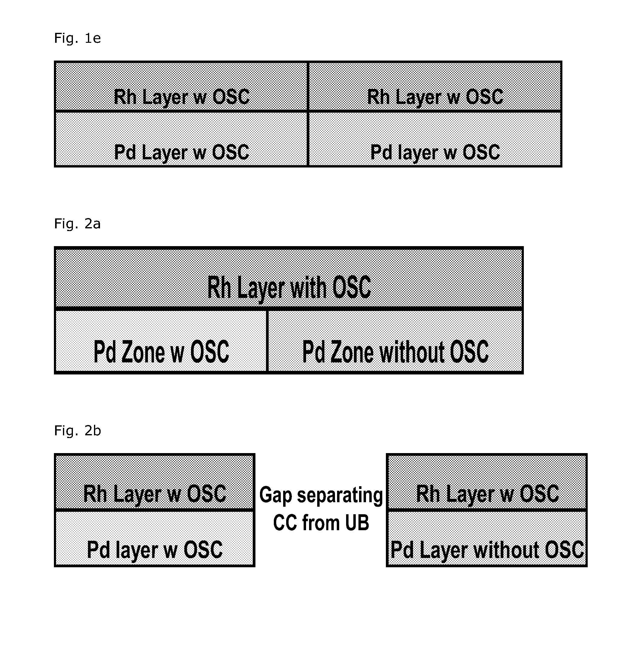
Disclosed herein is a layered, three-way conversion catalyst having the capability of simultaneously catalyzing the oxidation of hydrocarbons and carbon monoxide and the reduction of nitrogen oxides being separated in a front and rear portion is disclosed. Provided is a catalytic material of at least two front and two rear layers in conjunction with a substrate, where each of the layers includes a support, all layers comprise a platinum group metal component, and the rear bottom layer is substantially free of a ceria-containing oxygen storage component (OSC).

Description

TECHNICAL FIELD[0001]This invention pertains generally to layered catalysts used to treat gaseous streams containing hydrocarbons, carbon monoxide, and oxides of nitrogen. More specifically, this invention is directed to three-way-conversion (TWC) catalysts having more than one catalyst layer upstream and a multi-layer catalyst that is located downstream.BACKGROUND AND PRIOR ART[0002]Current TWC catalysts are used for mobile emission control from Otto engines. The technology is well developed with emission reduction capabilities of >99% for CO, HC (hydrocarbons) and NOx (nitrogen oxides) after heat up to operating temperatures of greater than 250° C. Typical TWC catalyst configurations consist of single brick or multi-brick systems in the exhaust line of the vehicle. If more than one catalyst is used, the catalysts can be located in a single converter, butted together, or separated by a defined space as in separate converters. A common design for large engines is to have one conv...

Claims


Application Information

Patent Timeline
Patent Type & Authority Patents(United States)
IPC IPC(8): F01N3/10B01J23/46B01D53/94
CPCB01D53/945B01D53/9477B01J23/464B01J23/63B01J35/0006B01J37/0244B01J37/0246B01J21/04B01J23/10B01J23/42B01J35/04B01J35/1014B01J35/1019B01D53/9472Y02T10/22B01D2255/1023B01D2255/1025B01D2255/9022B01D2255/908B01D2258/014B01J23/62B01J35/004Y02T10/12B01J35/19B01J35/56B01J35/613B01J35/39B01J35/615B01D53/94B01J23/46B01J35/00F01N3/28
Inventor NUNAN, JOHN G.KLINGMANN, RAOULANDERSEN, RYANCLARK, DAVIONMOSER, DAVID H.
Owner UMICORE AG & CO KG
Learn More