
Disk drive device improved in stiffness of fluid dynamic bearing

a fluid dynamic bearing and disk drive technology, applied in the direction of magnetic disk recording, recording information storage, instruments, etc., can solve the problems of deteriorating the accuracy of reading/writing magnetic data, the housing, and the shape of the disk drive device, so as to increase the number of thrust dynamic pressure grooves for generating thrust dynamic pressure, increase the effect of thrust dynamic pressure and increase the number of thrust dynamic pressur

Inactive Publication Date: 2012-11-20
SAMSUNG ELECTRO MECHANICS JAPAN ADVANCED TECHNOLOGY CO LTD
View PDF20 Cites 5 Cited by
  • Summary
  • Abstract
  • Description
  • Claims
  • Application Information

AI Technical Summary

Benefits of technology

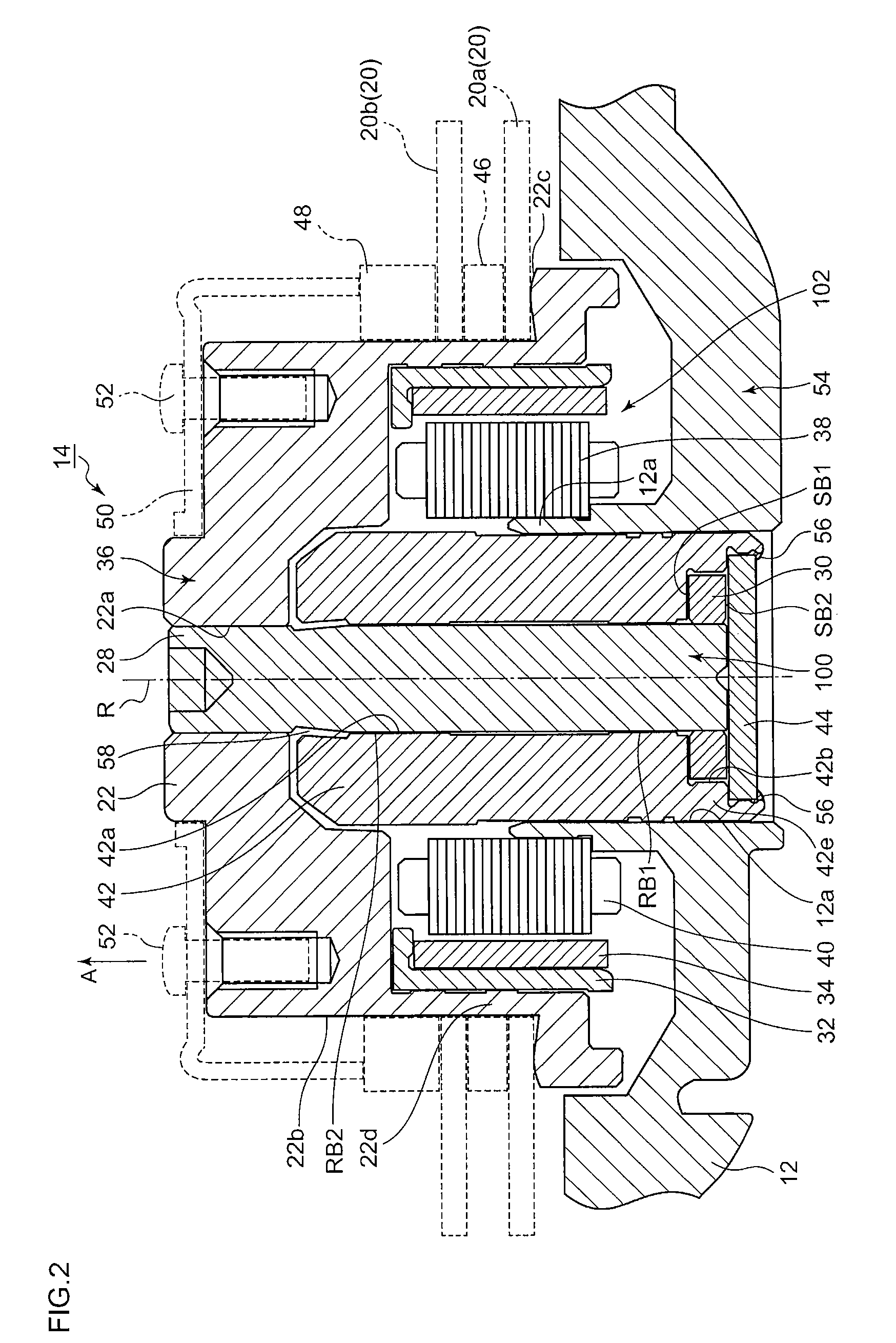
"The present invention provides a disk drive device that improves the stiffness of its fluid dynamic bearing without increasing its size or affecting its drive performance. This is achieved by a bearing unit that includes a shaft, a sleeve, and a radial space defined by the inner wall surface of the sleeve and the outer wall surface of the shaft. The bearing unit also includes a radial dynamic pressure groove and a thrust dynamic pressure groove that generate dynamic pressure to support the rotating recording disk. The device also includes a counter plate and a lubricant filled in the radial space and flange housing space, which further enhances the stiffness of the bearing. The arrangement space of the drive unit is also improved, resulting in a more compact device."

Problems solved by technology

However, in a disk drive device that is strongly needed to be small in size, it is undesirable that the housing, which forms the shape of the disk drive device, is made larger.
Alternatively, when the drive current is not increased, the maximum torque is decreased and the rotation becomes unstable accordingly, thereby sometimes deteriorating the accuracy of the reading / writing of magnetic data.

Method used


Image

  • Disk drive device improved in stiffness of fluid dynamic bearing
  • Disk drive device improved in stiffness of fluid dynamic bearing
  • Disk drive device improved in stiffness of fluid dynamic bearing

Examples


Embodiment Construction

[0022]The invention will now be described by reference to the preferred embodiments. This does not intend to limit the scope of the present invention, but to exemplify the invention.

[0023]Hereinafter, the preferred embodiments of the present invention will be described based on the accompanying drawings. The present embodiment is used in a brushless motor, which is mounted in a hard disk drive device (also simply referred to as an HDD or disk drive device) to drive a recording disk, and in a disk drive motor, etc., which is mounted in an optical disk recording and reproducing device (also simply referred to as a disk drive device), such as CD (Compact Disc) device or DVD (Digital Versatile Disc) device.

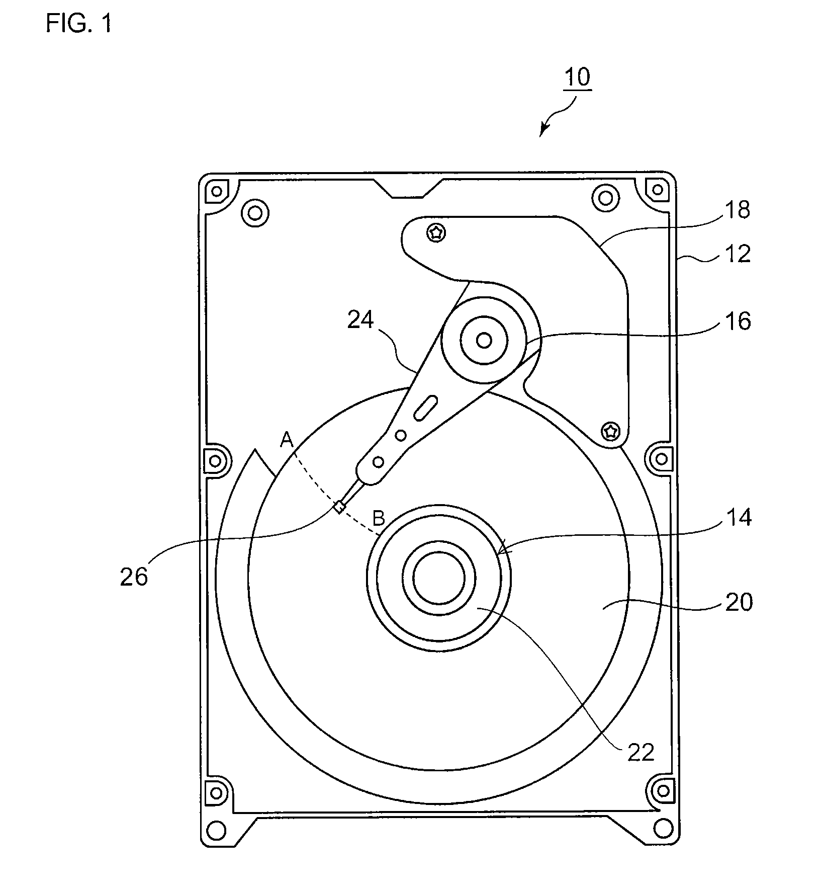
[0024]FIG. 1 is an illustrative view illustrating the internal structure of an HDD 10 (hereinafter, simply referred to as a disk drive device 10), an example of a disk drive device according to the present embodiment. FIG. 1 illustrates the state where the cover is removed to expose t...


PUM

PropertyMeasurementUnit
diameteraaaaaaaaaa
thicknessaaaaaaaaaa
thicknessaaaaaaaaaa

Abstract

A disk drive device includes a bearing unit and a drive unit. The bearing unit includes: a shaft; a sleeve configured to allow relative rotation, with the shaft as the axis; a flange projected in the radial direction of the shaft and configured to rotate integrally with the shaft; a flange housing space portion provided continuously from the sleeve and configured to rotatably house the flange; a counter plate structured with both a first surface, which faces the end surface in the axial direction of the flange and seals the flange housing space portion, and a second surface that is opposite to the first surface. The projected dimension of the flange is designed to be larger than the wall thickness of the flange surrounding wall portion in the radial direction of the flange, the flange surrounding wall portion defining the flange housing space portion.

Description

CROSS-REFERENCE TO RELATED APPLICATION[0001]This application is based upon and claims the benefit of priority from the prior Japanese Patent Application No. 2009-133407, filed on Jun. 2, 2009, the entire content of which is incorporated herein by reference.BACKGROUND OF THE INVENTION[0002]1. Field of the Invention[0003]The present invention relates to a disk drive device, in particular, to a disk drive device improved in the stiffness of a fluid dynamic bearing while suppressing an increase in the size and deterioration in the drive performance of the fluid dynamic bearing.[0004]2. Description of the Related Art[0005]Hard disk drives (HDDs) are media used in storage devices of computers, etc. Devices that drive such recording disks are collectively termed disk drive devices. A disk drive device rotates, at high speed, a recording disk on which recording tracks for recording magnetic data are formed by a brushless motor. A magnetic head, which executes read / write of magnetic data fro...

Claims


Application Information

Patent Timeline
Patent Type & Authority Patents(United States)
IPC IPC(8): G11B17/02H02K5/16
CPCG11B19/2036
Inventor NISHITANI, YUJI
Owner SAMSUNG ELECTRO MECHANICS JAPAN ADVANCED TECHNOLOGY CO LTD
Learn More