
Spark arrestor for processing metal workpieces

Inactive Publication Date: 2012-10-16
MOYER DENNIS
View PDF9 Cites 4 Cited by
  • Summary
  • Abstract
  • Description
  • Claims
  • Application Information

AI Technical Summary

Benefits of technology

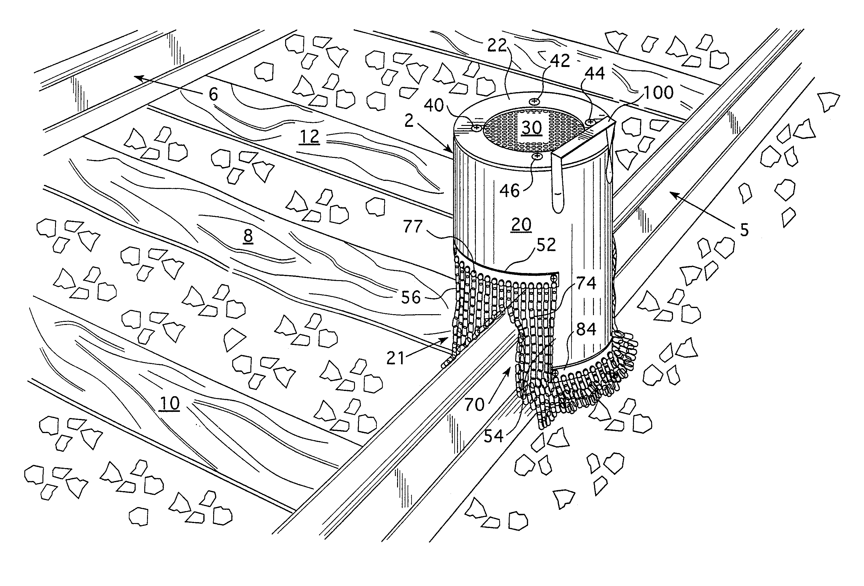
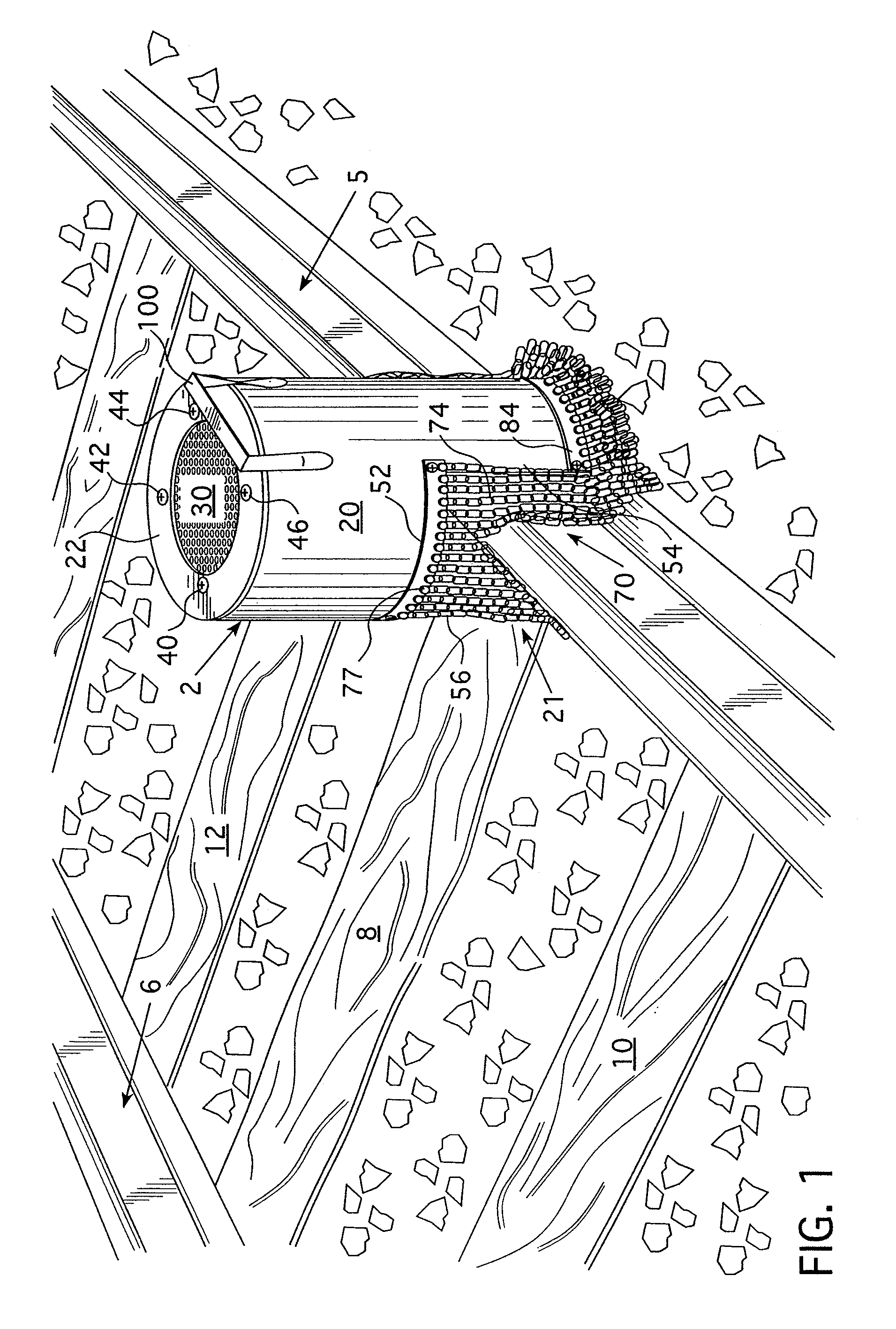
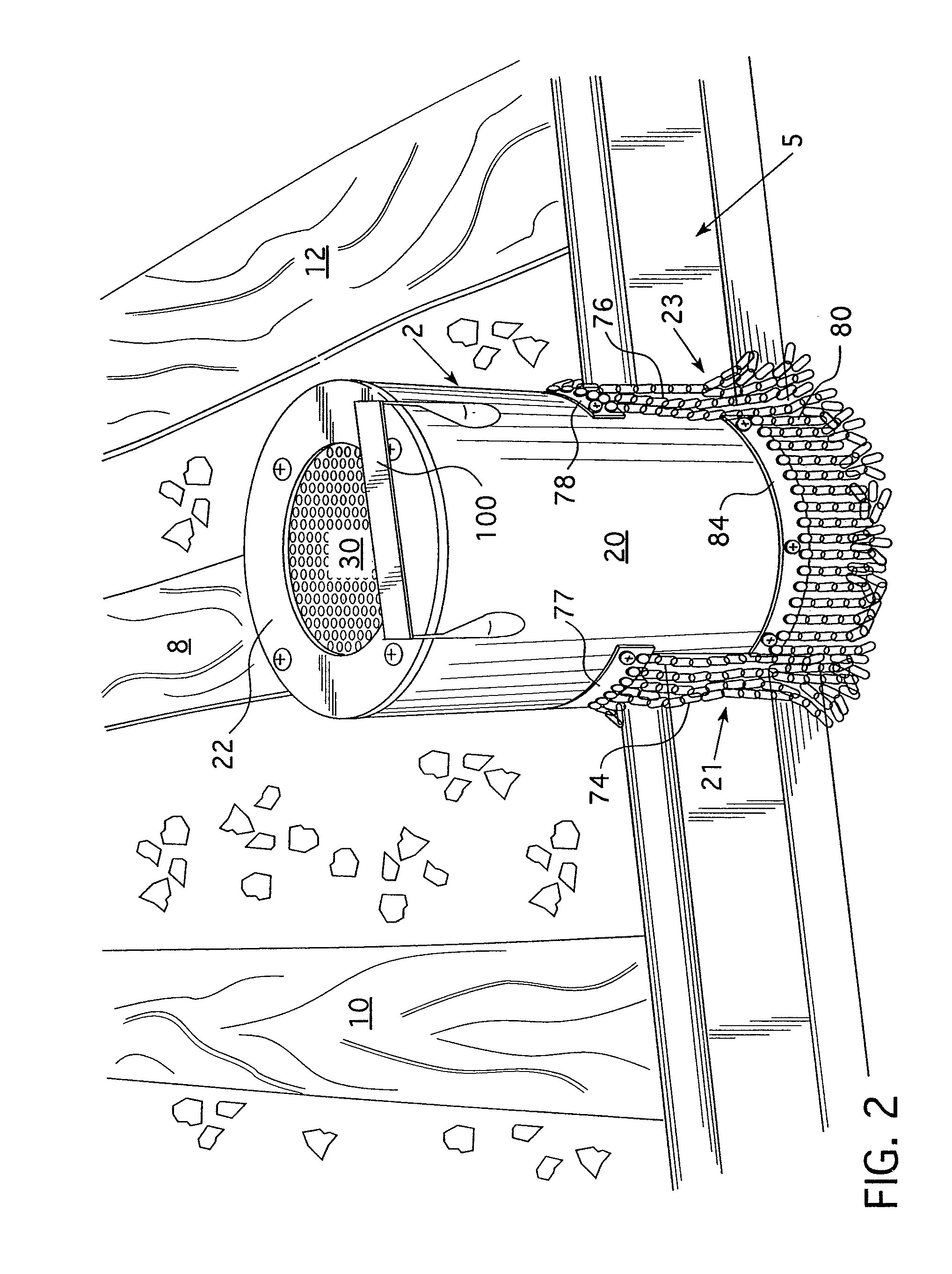
[0018]The above described problems have been solved by the present invention which provides a spark arrestor for salvaging railroad rails. An annular body has an upper end wall provided with a first opening and a lower end wall provided with a second opening. The annular body has a pair of generally aligned, circumferentially offset, downwardly open recesses which are structured to receive a portion of a railroad rail. Each of the recesses is operatively associated with a plurality of downwardly extending shield elements which extend downwardly beyond the upper surface of the rail. An opening is provided in the annular body for introduction of a cutting torch into the interior of the spark arrestor. Lateral portions of the annular body disposed between the downwardly open recesses have a second plurality of downwardly depending shield elements which serve to resist passage of flames and sparks thereunder. This results in substantially complete circumferential protection against undesired flame and spark escape from the interior of the spark arrestor during rail cutting operations.
[0019]It is an object of the present invention to provide a spark arrestor for use in processing metal workpieces while minimizing undesired escape of flames and sparks.
[0020]The spark arrestor structure described in the next proceeding paragraph may also be employed for a wide variety of uses other than railroad rails, in order to resist potential injury or damage to property resulting from sparks or flames created by the torch during the operation on a metal workpiece. For example, an elongated workpiece or plurality of workpieces, such as metal extrusions, said steel rods or any similar articles may be cut by the torch into a plurality of pieces of a desired length by cutting the elongated metal workpiece through the use of the torch. In another embodiment, the torch may be used to cut portions out of a workpiece, such as creating an opening in the workpiece without severing it from the parent stock. It may also be employed advantageously when workpieces are to be preheated.
[0022]It is a further object of the present invention to provide such apparatus which is readily portable and may be moved easily from one rail processing operation to another.
[0024]It is another object of the present invention to substantially reduce or eliminate burn hazards to workmen in the immediate area, and the risk of fire due to vegetation, railroad ties and other materials which could be damaged by exposure to flames or sparks.
[0025]It is yet another object of the present invention to provide such a system which is economical to create and employ and does not require extensive training of individuals who will be using the same.

Problems solved by technology

While such an embodiment will not provide the extent of protection as occurs with the use of such shield elements, in certain instances such as where the process will be practiced in an area where there is no significant amount of flammable material nearby and there is no great exposure for workers.

Method used


Image

  • Spark arrestor for processing metal workpieces
  • Spark arrestor for processing metal workpieces
  • Spark arrestor for processing metal workpieces

Examples


example

[0053]A non-limiting example of a currently preferred dimensional range for the shield is as follows. The overall axial height of the shield will be about 15 to 21 inches and the transverse diameter measured on the exterior will be about 9 to 13 inches. The openings for the rails will each be about 6 to 10 inches wide and will have a height of about 6 to 10 inches. The opening at the upper end will be about 6 to 8 inches across. Preferably, two stainless steel mesh grills, such as 30, will be provided in the top opening spaced from each other about ½ inch and having the patterns slightly offset from each other. The torch window 50 (FIG. 3) will preferably be an opening of about 2 to 4 inches wide and 6 to 8 inches high.

[0054]In connection with the use of the spark arrestor for metal workpieces other than railroad rails, essentially the same construction as disclosed and illustrated in FIGS. 1 through 7 may be employed for a wide variety of metal workpieces. The dimensioning of the s...


PUM


Abstract

A spark arrestor for processing metal workpieces includes an annular body having an upper end wall provided with a first opening and a lower end wall provided with a second opening. The annular body has a pair of generally aligned, circumferentially offset, downwardly open first recesses, each structured to be received over at least a portion of the metal workpiece. Each recess may have having a plurality of downwardly extending first shield elements. Lateral surfaces of the annular body disposed between the downwardly open first recesses have a pair of lateral second recesses which have a plurality of second shield elements extending downwardly therefrom. A torch receiving opening is provided in the annular body to facilitate insertion of the torch. The upper end wall first opening preferably has a grid structure to resist outward migration of sparks and flames from the interior of the spark arrestor.

Description

CROSS REFERENCE TO RELATED APPLICATION[0001]This application is a continuation-in-part of U.S. patent application Ser. No. 13 / 013,371 filed Jan. 25, 2011, entitled SPARK ARRESTOR FOR PROCESSING RAILROAD RAILS.BACKGROUND OF THE INVENTION[0002]1. Field of the Invention[0003]The present invention relates to a spark arrestor and, more specifically, it relates to a spark arrestor which may be employed in combination with a torch used to process portions of a metal workpiece in the process of cutting, heating or welding the metal workpiece while focusing upon resisting undesired spreading of flames or sparks to adjacent people or material in order to minimize or eliminate the risk of employee burns and fires.[0004]2. Description of the Prior Art[0005]In connection with conventional railroad operations, it is periodically necessary to remove railroad rails which have become worn or otherwise deteriorated and are not serviceable with the degree of safety required. It is conventional to use ...

Claims


Application Information

Patent Timeline
Patent Type & Authority Patents(United States)
IPC IPC(8): A62C8/00A47G5/04
CPCA62C8/08
Inventor MOYER, DENNIS
Owner MOYER DENNIS
Learn More