
High-resolution multi-level frequency channelizers

a frequency channelizer and high-resolution technology, applied in multiplex communication, instruments, optical elements, etc., can solve the problems of unsuitable insertion or deployment a form factor that is too large for insertion in fiber optic links, and a device with lower resolution

Inactive Publication Date: 2012-09-18
HRL LAB
View PDF15 Cites 13 Cited by
  • Summary
  • Abstract
  • Description
  • Claims
  • Application Information

AI Technical Summary

Benefits of technology

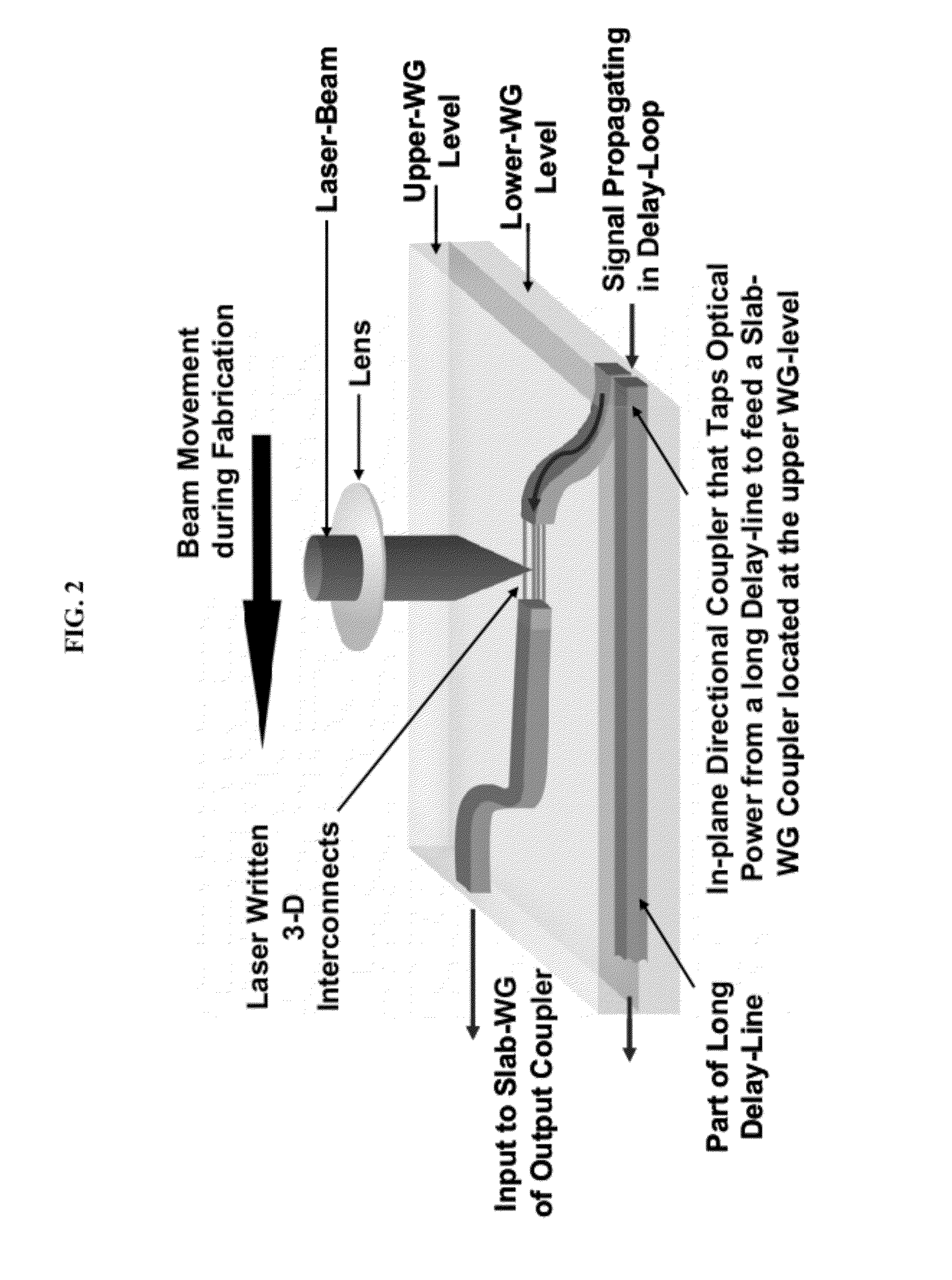
[0029]The optical interconnect be laser-written. For example, the optical interconnect can be effectively formed by translating a focal point of a laser beam from the first waveguide layer to the second waveguide layer, thereby generating regions of material with increased optical refractive index.
[0036]In some embodiments, the optical interconnect is formed by translating a focal point of a laser beam from a filter-tap to a slab waveguide coupler, thereby generating a region with increased optical refractive index.
[0040]A suitable laser beam can be in the UV region or the near-IR region. In some embodiments, the laser beam is pulsed with a pulse width selected from about 10-1000 fs, e.g. about 100-500 fs. This method of writing an optical interconnect enables the formation of one or more three-dimensional optical interconnects, which can be useful when the first and second waveguide layers are stacked.

Problems solved by technology

While simpler in fabrication and less expensive than AWGs, these devices typically have lower resolution and have a form factor that is too large for insertion in fiber optic links.
Because of their operational dependence on free-space optics, these devices are also very sensitive to temperature and generally to vibration / shock, making them unsuitable for insertion or deployment in a fiber optic link.

Method used


Image

  • High-resolution multi-level frequency channelizers
  • High-resolution multi-level frequency channelizers
  • High-resolution multi-level frequency channelizers

Examples


Embodiment Construction

[0046]The apparatus and methods of the present invention will now be described in detail by reference to various non-limiting embodiments of the invention.

[0047]Unless otherwise indicated, all numbers expressing dimensions, frequencies, efficiencies, and so forth used in the specification and claims are to be understood as being modified in all instances by the term “about.” Without limiting the application of the doctrine of equivalents to the scope of the claims, each numerical parameter should at least be construed in light of the number of significant digits and by applying ordinary rounding techniques.

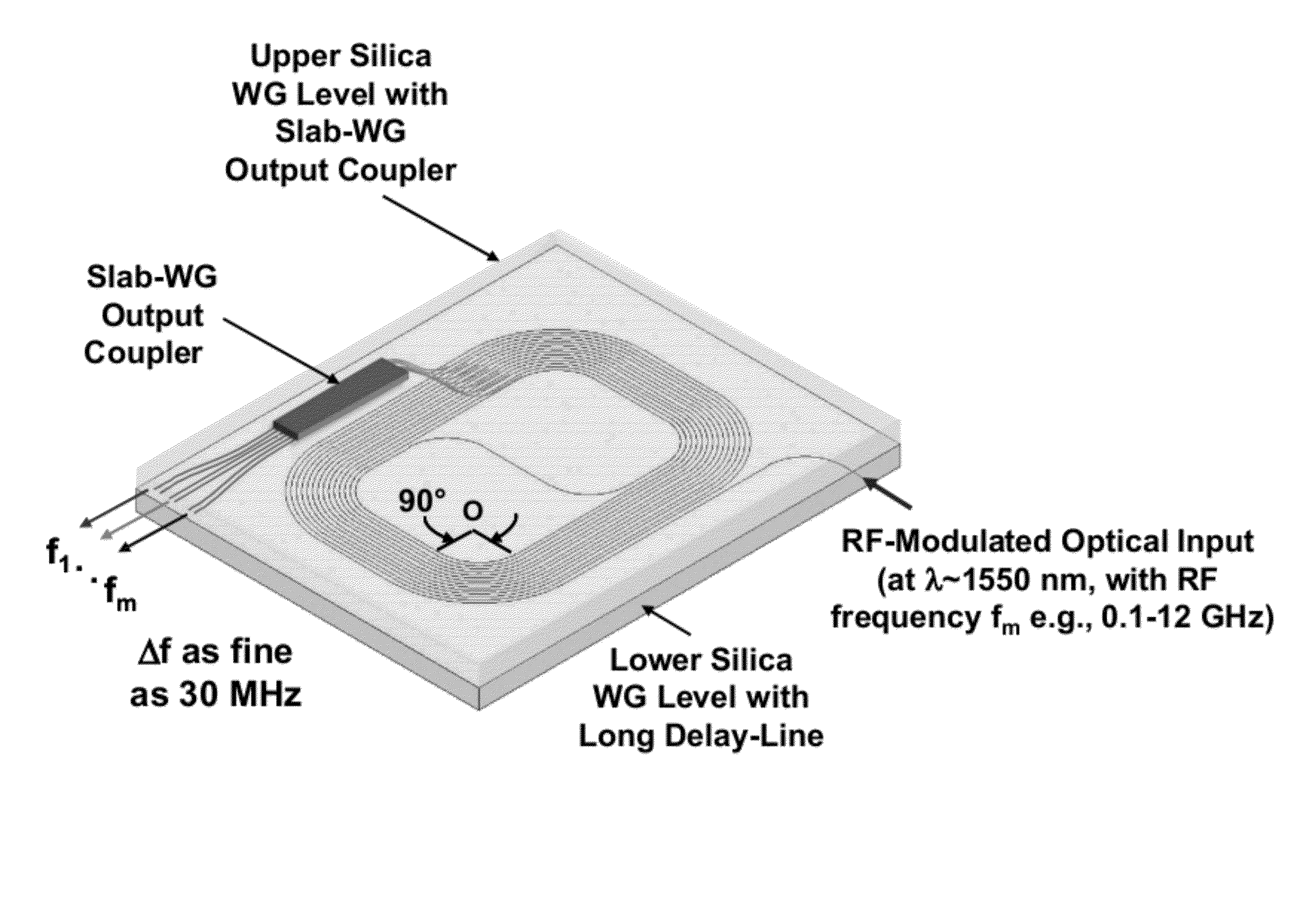
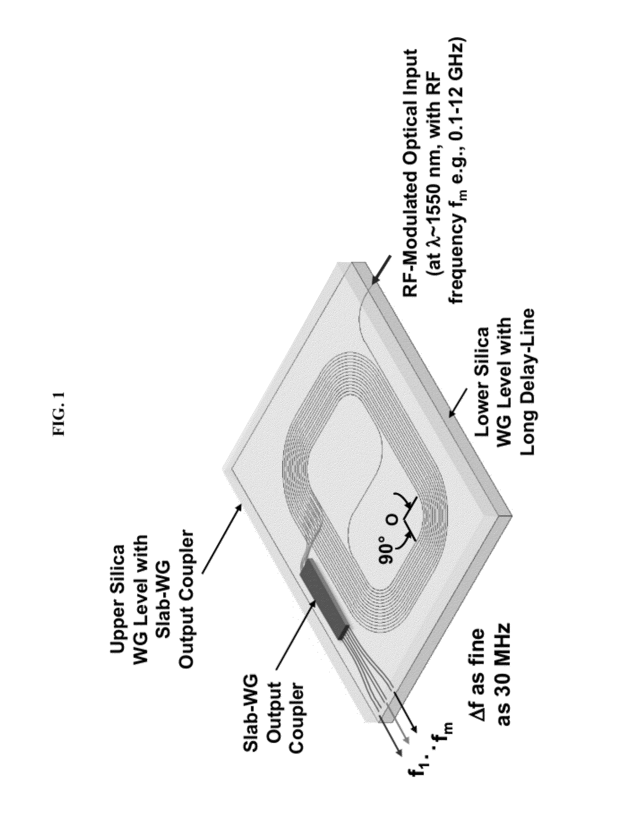
[0048]In some variations, this invention provides an approach for fabricating photonic-frequency channelizers, such as radio-frequency (RF) channelizers or spectrum analyzers, formed on multiple layers of waveguides. “Channelization” refers to the filtering or division of a broadband signal into narrower frequency-bands, or channels. In some embodiments, a frequency channelizer of...


PUM


Abstract

In some variations, the present invention provides a method for forming a chip-scale photonic frequency channelizer or spectrum analyzer. A low-loss waveguide forms a long delay-line in a first level, from which a large number of filter-taps form narrow channel passbands. Multi-dimensional laser-written waveguides feed a slab waveguide coupler located at a stacked, second level. A chip-scale RF-photonic spectrum analyzer provided by this invention has extremely high resolution, such as a passband width of about 30 MHz over a free spectral range of 12 GHz, while occupying a device footprint of only about 10 cm2 area.

Description

FIELD OF THE INVENTION[0001]The present invention relates generally to frequency channelization, and specifically to high-resolution frequency channelizers and spectrum analyzers.BACKGROUND OF THE INVENTION[0002]The ever-increasing demand for broadband communication systems has led to optical-transmission systems based on optical waveguides such as fiber optics and optical-processing elements. Generally, in high-performance communication systems, photons continue to supplant electrons as messengers. In defense-related systems, one can encounter threats over a broad spectrum of radio frequencies. The systems need to cover the spectrum with sufficient selectivity to separate simultaneously received signals that are closely spaced in frequency. These requirements can be met through frequency channelization.[0003]Optical wavelengths (or frequencies) can be separated (demultiplexed) or recombined (multiplexed) through physical phenomena known as refraction and diffraction. Many multiplex...

Claims


Application Information

Patent Timeline
IPC IPC(8): G02B6/26H04J14/00
CPCG02B6/12014H04J14/0201
Inventor NG, WILLIE W.
Owner HRL LAB
Learn More