
Liquid crystal display

a liquid crystal display and display technology, applied in the field of liquid crystal display, can solve problems such as possible malfunction of the touch panel, and achieve the effect of eliminating a virtual image, increasing the touch recognition rate and accuracy of a dead zon

Active Publication Date: 2012-09-18
LG DISPLAY CO LTD
View PDF2 Cites 20 Cited by
  • Summary
  • Abstract
  • Description
  • Claims
  • Application Information

AI Technical Summary

Benefits of technology

[0008]Accordingly, the present invention has been made to solve the above-mentioned problems occurring in the prior art, and an aspect of the present invention is to provide an apparatus and method of multi-touch sensing which can increase the touch recognition rate and accuracy of a dead zone and eliminate a virtual image.

Problems solved by technology

However, if a multi-touch is generated by two or more substantially simultaneous contact points, the touch panel might malfunction or any one of the touches can be selected by a pre-set program.
Also, the multi-touch recognition device may generate a virtual image due to the shadow effect of a real touch object upon multi-touch, and the coordinates of such a virtual image may be wrongly recognized as the coordinates of a real touch position.

Method used


Image

  • Liquid crystal display
  • Liquid crystal display
  • Liquid crystal display

Examples


Embodiment Construction

[0027]The above and other aspects and features of the present invention will become more apparent by describing exemplary embodiments thereof with reference to the attached drawings.

[0028]Hereinafter, implementations of this document will be described in detail with reference to FIGS. 1 to 16.

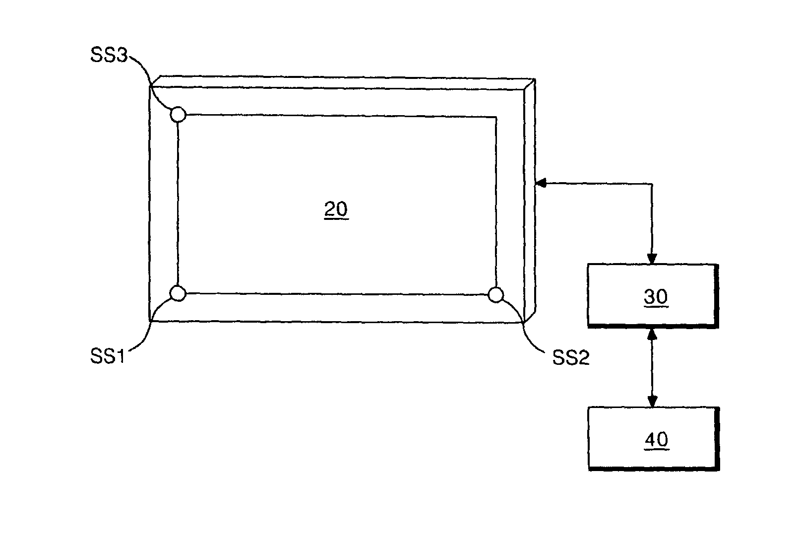
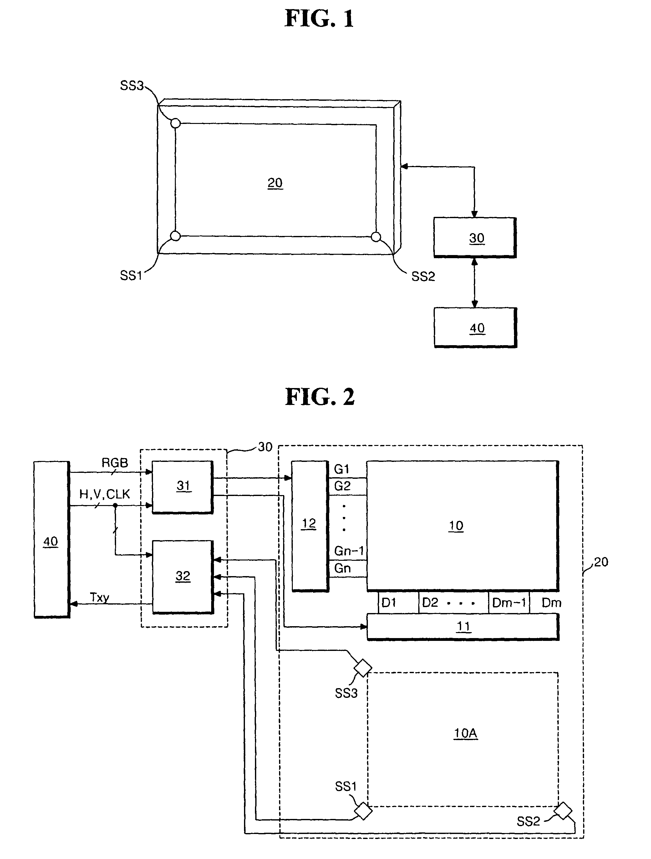
[0029]Referring to FIGS. 1 to 4, a multi-touch sensing apparatus according to an exemplary embodiment of the present invention includes a control board 30 which controls the touch and display module 20 and calculates the coordinates of a touch point, and a system 40 for supplying data RGB which are to be displayed along with a timing signal, to the control board 30.

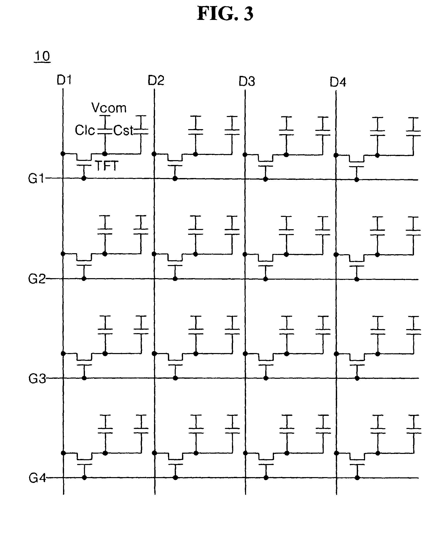
[0030]The touch and display module 20 includes a display panel 10 having a pixel display panel 10 having a pixel array 10A on which a picture is displayed, a source driver 11 for supplying data voltages to data lines D1 to Dm of the display panel 10, a gate driver 12 for supplying scan pulses to gate lines G1 to Gn of the display pan...


PUM


Abstract

A multi-touch sensing method and apparatus are described. The multi-touch sensing method includes: storing, in a memory, coordinate values of a first dead zone and coordinate values of a second dead zone existing between first and second pair of image sensors, respectively; calculating coordinate values of touch points from images obtained by the first and second pairs of image sensors; comparing the coordinate values of the touch point and the coordinate values of the dead zones to identify the location of the dead zone to which the touch point belongs; selecting the coordinate values calculated in the third step if the coordinate values of the touch point belong to the first dead zone; and selecting the coordinate values calculated in the second step if the coordinate values of the touch point belong to the second dead zone.

Description

[0001]This application claims the benefit of Korean Patent Application No. 10-2008-0129572 filed on Dec. 18, 2008, which is incorporated herein by reference for all purposes as it fully set forth herein.BACKGROUND OF THE INVENTION[0002]1. Field of the Invention[0003]This document relates to a liquid crystal display, and more particularly, to an apparatus and method of multi-touch sensing which can increase the touch recognition rate and accuracy of a dead zone and eliminate a virtual image.[0004]2. Description of the Related Art[0005]Generally, a touch panel is a type of user interface that is attached to a display device with the property that an electrical characteristic thereof is changed at a contact point where a hand or a pen touches the panel. Touch panels have been used in various applications, such as in small portable terminals, office equipment and the like. However, if a multi-touch is generated by two or more substantially simultaneous contact points, the touch panel mi...

Claims


Application Information

Patent Timeline
Patent Type & Authority Patents(United States)
IPC IPC(8): G06F3/041
CPCG06F3/0428G06F3/0488G06F2203/04808G06F3/0304G06F2203/04104G06F2203/04108G06F3/03547G06F3/04166
Inventor SOHN, MINHOCHOI, JONGSEONGJANG, HYUNGUKLEE, SANGRAEHAN, JAEJUNGBAE, SANGHYUCKYU, BYUNGCHUN
Owner LG DISPLAY CO LTD
Learn More