Simulating device

a technology of simulating devices and fire effects, applied in the field of simulating devices, can solve the problems of high cost, complicated devices of this type, and mechanical sweeps, and achieve the effects of high contrast relationship, efficient and reliable electronic control, and large distance range for the action of the devi

Active Publication Date: 2012-09-18
SAAB AB
View PDF12 Cites 0 Cited by
  • Summary
  • Abstract
  • Description
  • Claims
  • Application Information

AI Technical Summary

Benefits of technology

[0010]This means that no complicated and expensive mechanical arrangement is necessary for providing different information to different sections of a predetermined space through said light lobe. Furthermore, more accurate and sophisticated information may in this way easily be obtained by simply controlling the elements of said two-dimensional array. The problems with restrictions with respect to time and position caused by the sequential nature of a sweep may also be eliminated, since there is no need to carry out any mechanically controlled sweep any longer. By controlling elements of such an array a nearly indefinite number of ways to position the transmission of light codes may be obtained.
[0024]According to another preferred embodiment of the invention said elements are micro-mirrors tiltably arranged in an array, and said first state of these micro-mirrors is letting through in said main direction by reflecting the light inciding thereupon in a pre-determined direction and the second state by diverting said light so that dark regions will be created thereby in a cross-section of said light lobe. An advantage of using such micro-mirrors is that a high contrast relationship, i.e. maximum of light in said main direction in the first state / minimum of light in said main direction in the second state, is obtainable, which means that the distance range for the action of the device may be large. This range is defined by the shortest possible distance in said main direction to the device at which said information of the light lobe does not reach a receiver in said second state of the elements and the largest possible distance at which the information of the light lobe may reach a receiver in said first state of the elements. Another advantage of micro-mirrors is that the switch speed thereof is extremely high.

Problems solved by technology

Devices of the type defined in the introduction used today have means creating a thin line of laser light, and an expensive mechanical arrangement is used for obtaining a laser lobe formed by sweeping of this line in for instance a horizontal direction.
If there also is a desire to obtain sweeping in a direction perpendicular thereto, such as sweeping both in horizontal and vertical direction, a device of this type becomes extremely complicated.
Another disadvantage of a device of that type is that a mechanically controlled sweep also means a restriction of the possibilities to send out information simulating fire effects with respect to time and position as a consequence of the sequential nature of the sweep (for instance from the right to the left and / or from the top to the bottom).

Method used


Image

  • Simulating device
  • Simulating device
  • Simulating device

Examples


Embodiment Construction

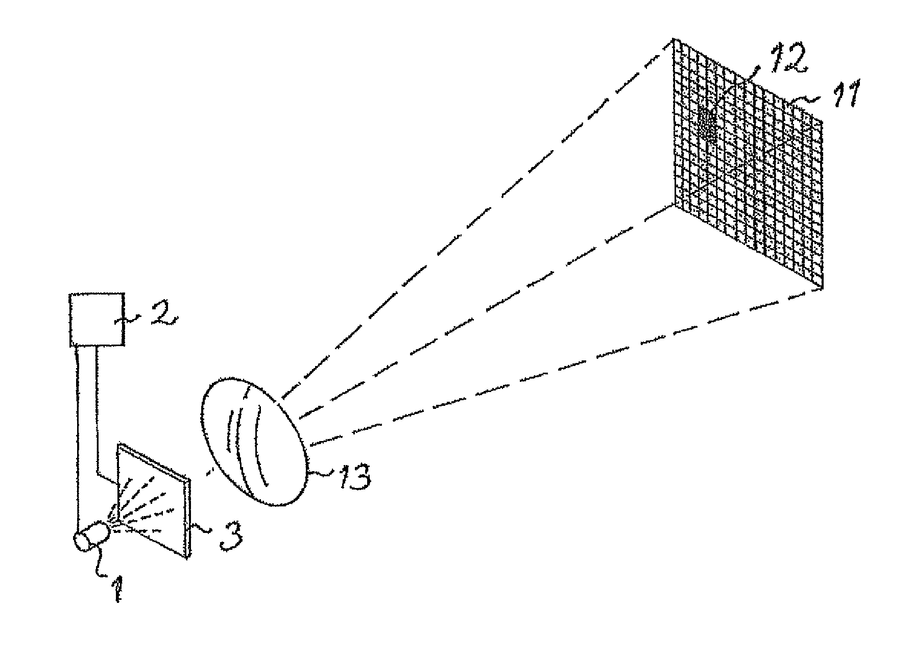
[0039]A device for simulating fire effects in military or civilian combat training according to the present invention is schematically shown in FIG. 1. This device comprises a light source, for example in the form of a laser or LED (light emitting diode). In this description a laser 1 adapted to emit infra red laser pulses with a certain power has been chosen as the light source. The device comprises further a unit 2 adapted to control the laser to deliver desired information by determining the intervals between consecutive pulses. A two-dimensional array 3 of elements electronically controllable is arranged in the path of the laser beams from the laser. These elements are controllable to assume either a first state of letting laser light inciding thereupon through in a main direction of a laser lobe formed by laser beams from the laser or a second state of not letting laser light inciding thereupon through in said main direction. The control unit 2 is adapted to. control said eleme...


PUM


Abstract

A device for simulating fire effects in military or civilian combat training. The device includes a light source configured to produce light beams and a light source control adapted to control a light lobe formed by the light beams from the light source. The light source control includes a two-dimensional array of elements electronically controllable to assume a selected state among at least a first state of letting through light incident thereupon in a main direction of the light lobe or a second state of not letting through the light incident thereupon in the main direction, and a unit adapted to control the elements for designing the spatial propagation of the light lobe.

Description

TECHNICAL FIELD OF THE INVENTION[0001]The present invention relates to a device for simulating fire effects in military or civilian combat training, said device comprising a light source and means adapted to control a light lobe formed by light beams from said light source.[0002]Such a device is used when training soldiers in military or civilian combat.[0003]“Simulating fire effects” does here mean simulating the effects of different weapons and military equipment, such as firearms, sector charges and other types of directed fire, in the sense that the device shall cause or assist to cause the same effect on participants, such as soldiers, vehicles or the like, in the military or civilian exercise as would such weapons or equipments have done in a real military or civilian combat.[0004]The information sent out by the light source, for example an infra red light emitting laser, is in the form of a code with the information formed by the length of the time periods between consecutive...

Claims


Application Information

Patent Timeline
Patent Type & Authority Patents(United States)
IPC IPC(8): F41A33/00
CPCG09B9/003
Inventor STENNERT, HAKANEMRICSON, INGEMARFORSELIUS, MATS
Owner SAAB AB
Why Eureka
Try Eureka