
Parallel printing system having flow control in a virtual disk transfer system

a virtual disk transfer and parallel printing technology, applied in the field of parallel printing systems, can solve the problems of limited processing speed, limited software optimization, and high processing cost, and achieve the effects of reducing the cost of software optimization, and improving the efficiency of the system

Active Publication Date: 2012-09-11
XEROX CORP
View PDF23 Cites 7 Cited by
  • Summary
  • Abstract
  • Description
  • Claims
  • Application Information

AI Technical Summary

Benefits of technology

This approach enhances processing efficiency and speed by allowing parallel RIP node processing with granularity from page to job level, reducing latency, and maintaining system performance with multiple languages without conversion, while optimizing memory management and auto-discovery of resources.

Problems solved by technology

First, faster serial processing methods suggest optimizing the software and using faster and more expensive processors.
Second, job parallel processing sends separate jobs to separate systems and then prints them on a common printer.
Software optimization has its limits and faster processors are also limited by currently available technology.
Job parallel processing results in poor single job performance, unpredictable job time and reduced throughput when there is only one long job in the queue.
The existing PDF-based solutions are slow due to their need to often convert from a different input language into PDF and then write the PDF file into an input spool disk.
Page parallel processing has suffered from the inefficiencies of a throughput disadvantage because per job overhead occurs on a per page basis.
However, it can be easily appreciated that where the jobs require substantially different processing times, waits will necessarily occur and overall system efficiency will suffer.

Method used


Image

  • Parallel printing system having flow control in a virtual disk transfer system
  • Parallel printing system having flow control in a virtual disk transfer system
  • Parallel printing system having flow control in a virtual disk transfer system

Examples


Embodiment Construction

[0029]While the present invention will hereinafter be described in connection with preferred embodiments thereof, it will be understood that it is not intended to limit the invention to those embodiments. On the contrary, it is intended to cover all alternatives, modifications and equivalents as may be included within the spirit and scope of the invention as defined in the appended claims.

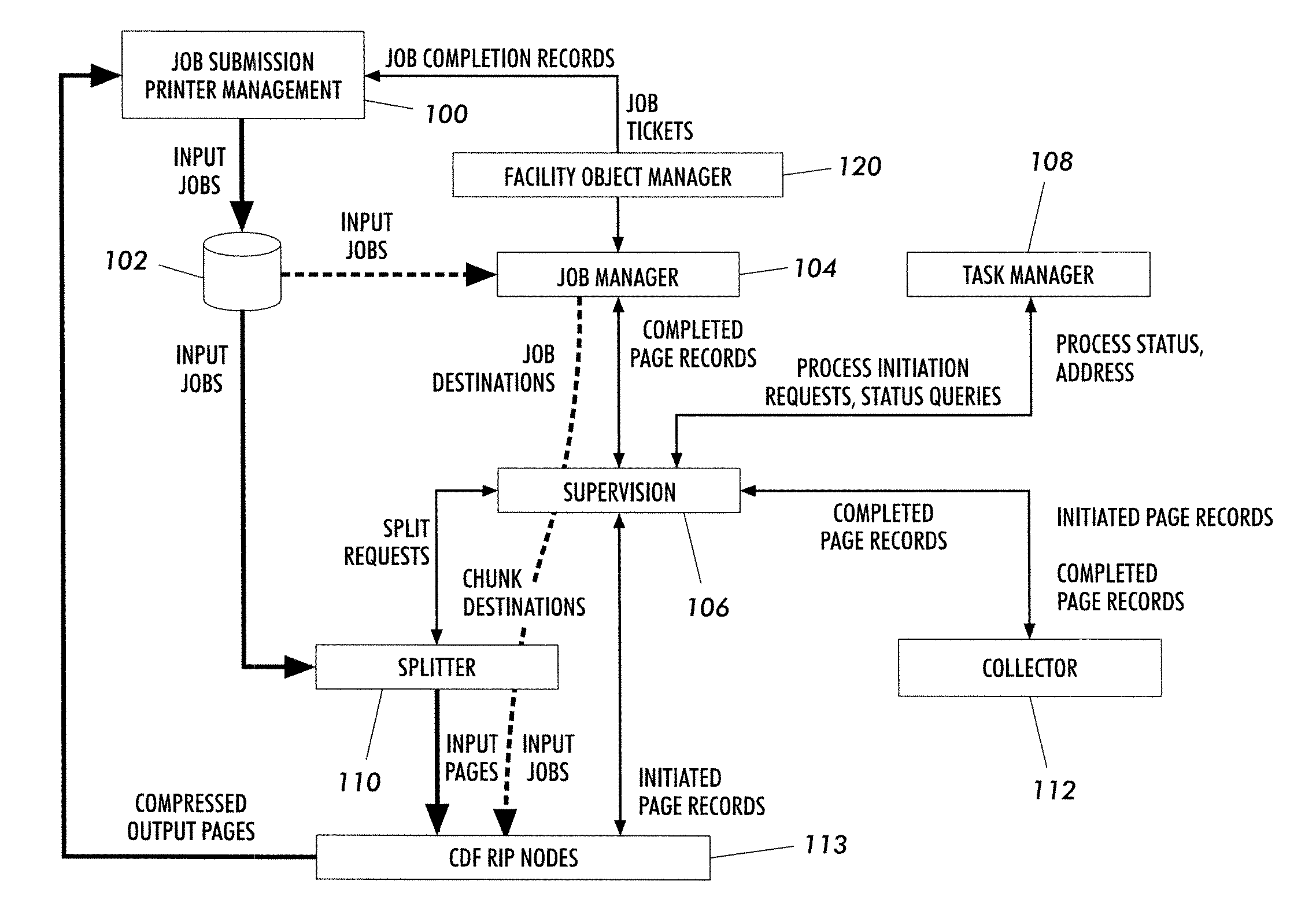
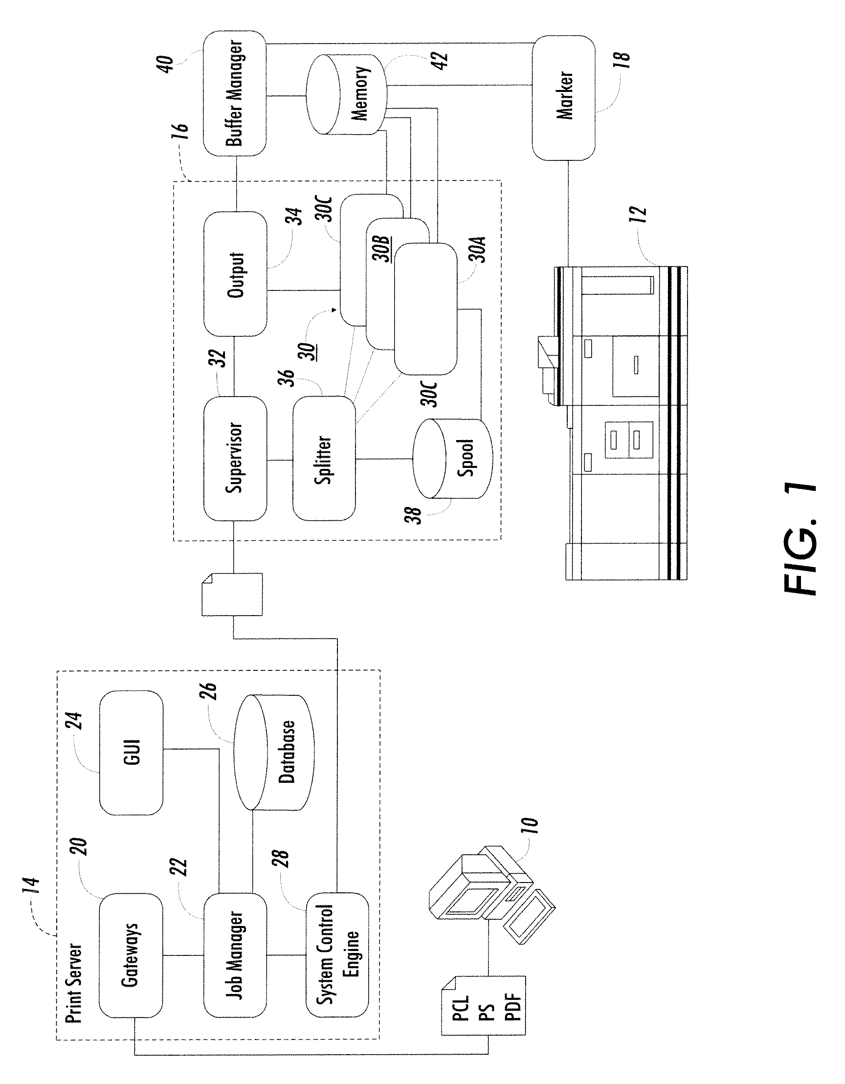
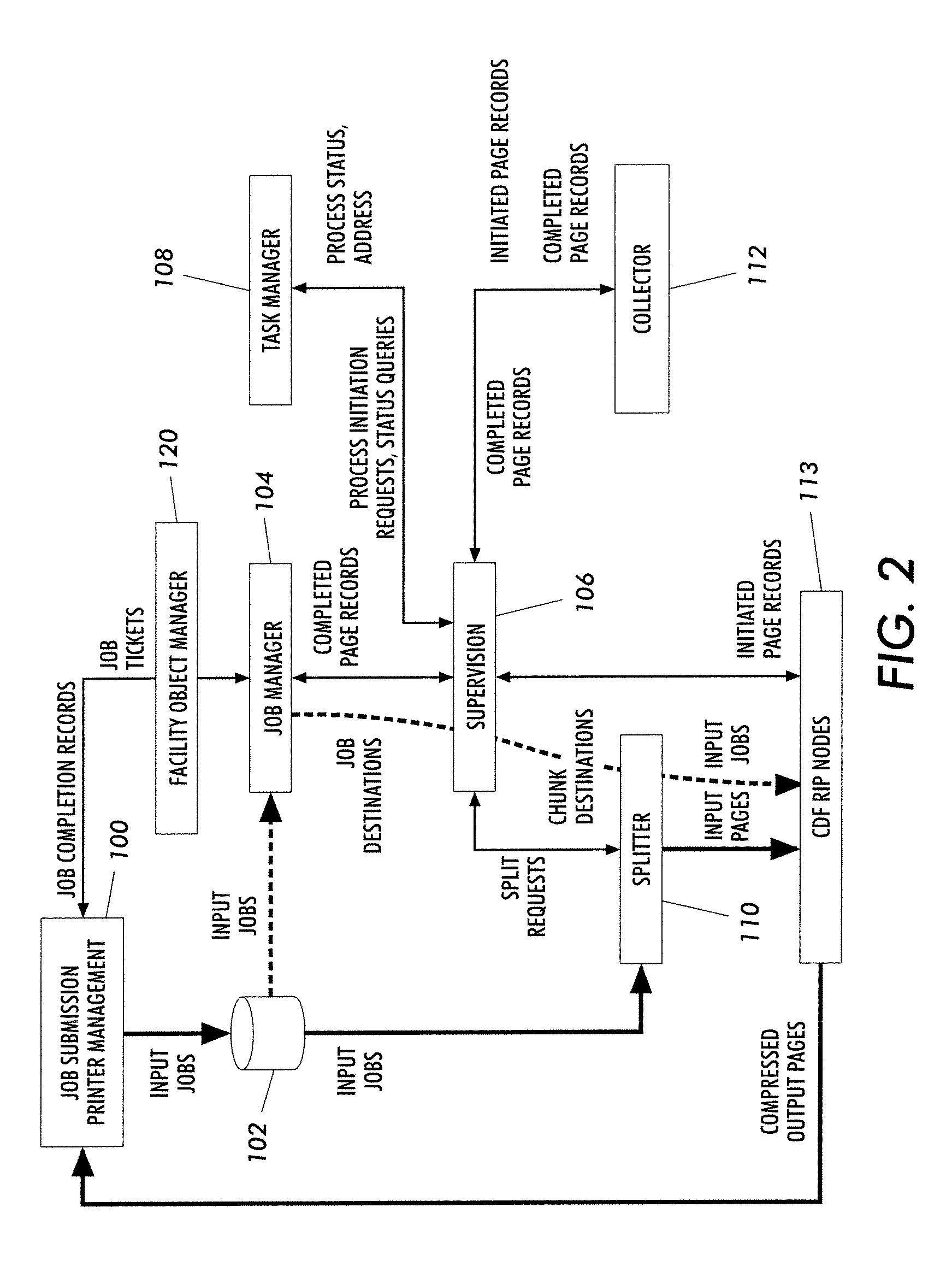
[0030]The present invention addresses the continuing need for faster printing systems—particularly systems where every page can be color and different. The system exploits parallelism to facilitate its speed, but especially an implementation of parallelism not known in prior art printing systems which had been limited to job parallelism or page parallelism. The subject invention uses an intermediate level of parallelism herein defined as “chunk” parallelism. A chunk of print job data is intended to comprise a collection of rasterizable data of at least one page and not more than one job. Job parall...


PUM


Abstract

A printing system comprised of a printer, a plurality of processing nodes, each processing node being disposed for processing a portion of a print job into a printer dependent format, and a processing manager for spooling the print job into selectively sized chunks and assigning the chunks to selected ones of the nodes for parallel processing of the chunks by the processing nodes into the printer dependent format. The chunks are selectively sized from at least one page to an entire size of the print job in accordance with predetermined splitting factors for enhancing printer printing efficiency. The operating of the printing system includes a method for parallel processing of a print job with a plurality of processing nodes into a printer-ready format for printing the print job, wherein the processing nodes communicate with a virtual disk transfer system and control usage thereof by monitoring available space in the virtual disk transfer system.

Description

[0001]This application is a continuation-in-part of U.S. patent application Ser. No. 10 / 407,564 now U.S. Pat. No. 7,872,767, filed in the name of Klassen, on Apr. 4, 2003.FIELD OF THE INVENTION[0002]The subject invention relates to printing systems, their architecture and processing steps and, more particularly, to producing electronic images in a manner to drive digital printers more efficiently and faster.BACKGROUND OF THE INVENTION[0003]Generating print-ready documents to be printed by a printing system involves acquiring the information (content, graphics, production specs, etc.) required to view, process and output the desired document in an electronic form understandable by a print engine. Such systems can range from those that are simple and modestly expensive such as are well known to consumer users of personal computer systems, up to commercial printing systems that are capable of generating in the range of one hundred pages per minute in full color. All systems, though, ha...

Claims


Application Information

Patent Timeline
Patent Type & Authority Patents(United States)
IPC IPC(8): G06K15/00G06F3/12
CPCG06F3/1212G06F3/124G06F3/1285G06F3/1206
Inventor KLASSEN, R. VICTORGENTNER, JESS R.
Owner XEROX CORP
Learn More