Bonding lead
a technology of lead and bonding, applied in the field of joint, to achieve the effect of preventing the compression set (or creep) of the barrier layer
- Summary
- Abstract
- Description
- Claims
- Application Information
AI Technical Summary
Benefits of technology
Problems solved by technology
Method used
Image
Examples
Embodiment Construction
)
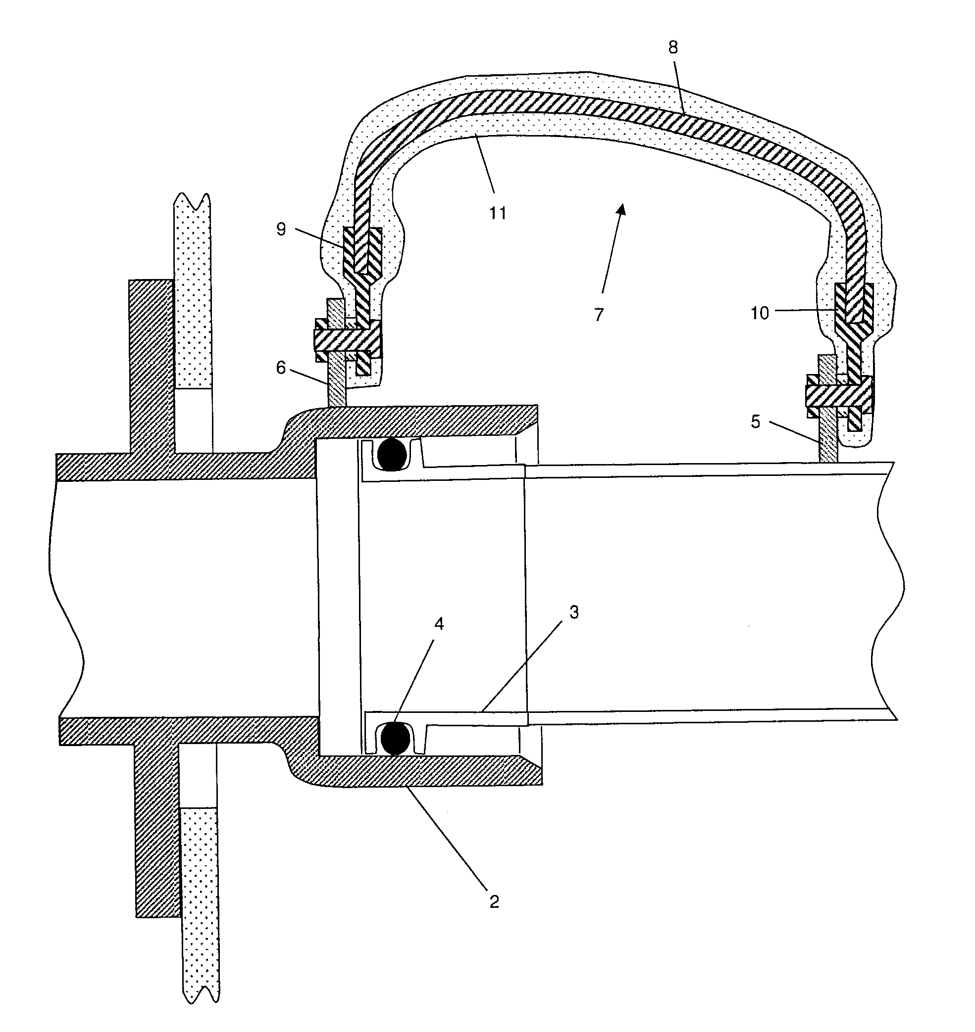
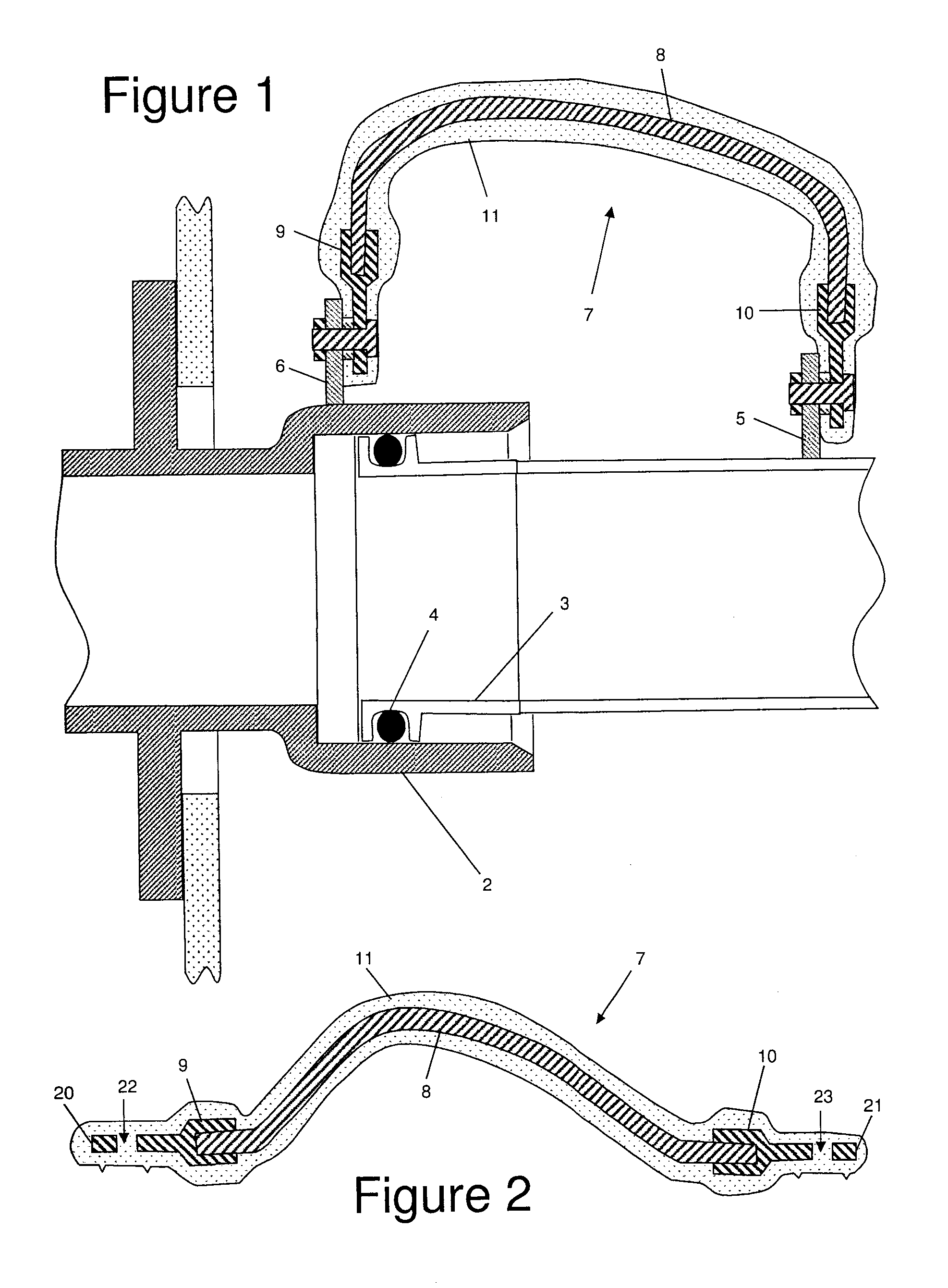
[0023]FIG. 1 shows fuel pipe joint on an aircraft. The joint comprises a socket 2, in which a pipe end fitting 3 is located, an O-ring seal 4 sealing the contact between the socket and the pipe end fitting, and a bonding lug 5 welded to the fuel pipe connected to the pipe end fitting 3. A further bonding lug 6 is machined on the socket arrangement and a bonding lead 7 is arranged between the two lugs 5, 6 electrically connecting one side of the joint to the other.
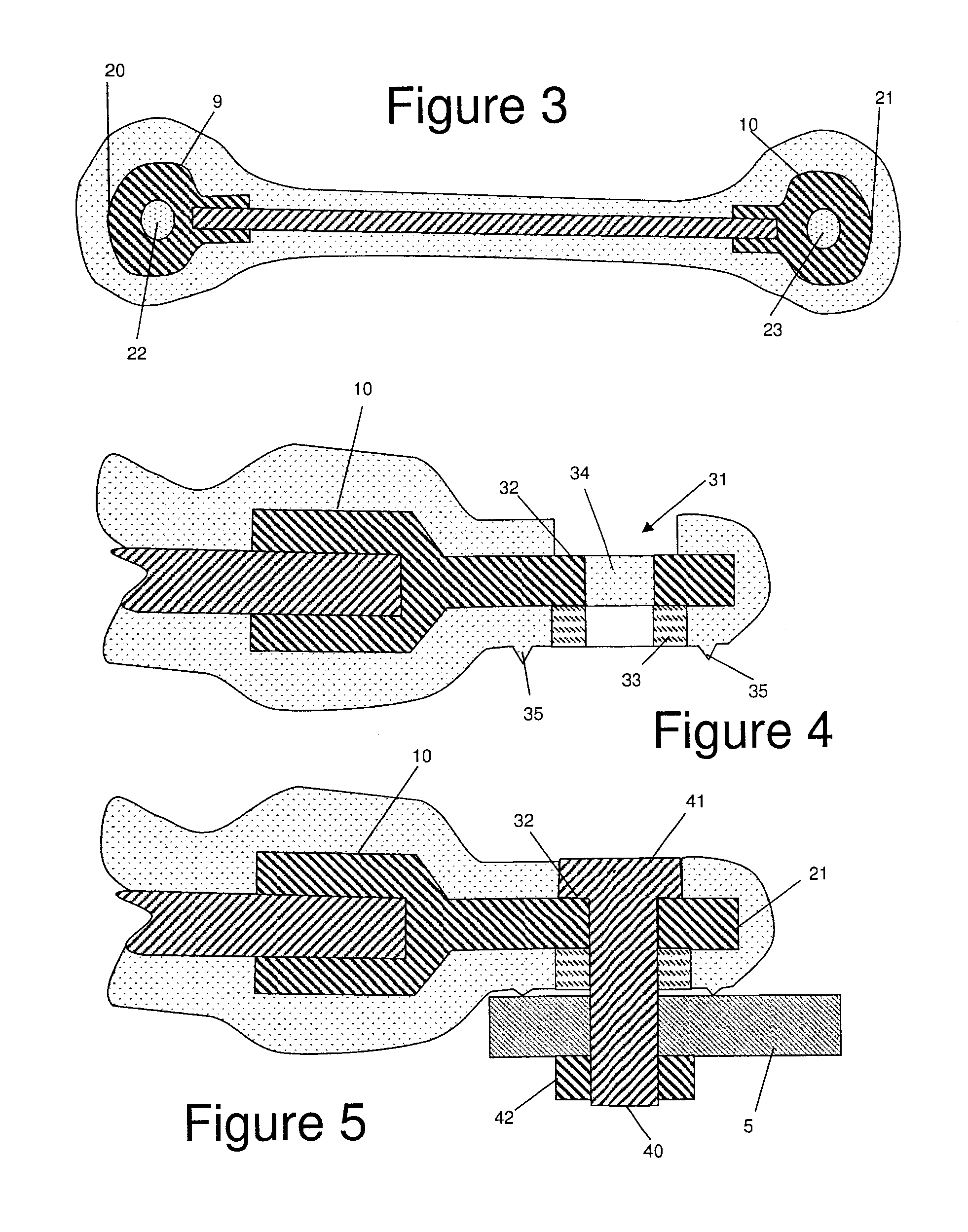
[0024]The bonding lead 7 has a conductive core comprising a multi-stranded cable 8 and a pair of connection brackets 9, 10 which are crimped to the cable 8. As shown in FIGS. 2 and 3, the conductive core is elongate and has a pair of tips or end faces 20, 21 at the extremities of its length.
[0025]Typically the cable 8 and brackets 9, 10 are both formed from a metal such as copper, but optionally the cable and / or the brackets 9, 10 may be formed from spun long carbon nanotubes or carbon fibres which have a high breaking str...
PUM
| Property | Measurement | Unit |
|---|---|---|
| Shore hardness | aaaaa | aaaaa |
| length | aaaaa | aaaaa |
| elastomeric | aaaaa | aaaaa |
Abstract
Description
Claims
Application Information
 - R&D
- Intellectual Property
- Life Sciences
- Materials
- Tech Scout
- Unparalleled Data Quality
- Higher Quality Content
- 60% Fewer Hallucinations
Browse by: Latest US Patents, China's latest patents, Technical Efficacy Thesaurus, Application Domain, Technology Topic, Popular Technical Reports.
© 2025 PatSnap. All rights reserved.Legal|Privacy policy|Modern Slavery Act Transparency Statement|Sitemap|About US| Contact US: help@patsnap.com


