Using compressed intake air to clean engine exhaust gas recirculation cooler

a technology of compressed intake air and engine exhaust gas, which is applied in the direction of machines/engines, grain treatment, applications, etc., can solve the problems of reducing the ability of recirculated exhaust gas to improve emission, reducing the heat transfer ability of egr cooler, and shortening the time period , to achieve the effect of improving the emission performance of diesel engines and shortening the time period

Inactive Publication Date: 2012-08-28
FORD GLOBAL TECH LLC
View PDF20 Cites 14 Cited by
  • Summary
  • Abstract
  • Description
  • Claims
  • Application Information

AI Technical Summary

Benefits of technology

[0001]Exhaust gas recirculation is used to improve emission performance of diesel engines. Prior to being introduced into engine combustion chambers, the exhaust gas may be circulated through one or more EGR coolers. Due to the low temperature environment and flow characteristics of the EGR cooler, soot particles contained in the exhaust gas may be deposited onto walls of the EGR cooler to form a film of soot, often in a relatively short period of time, decreasing the heat transfer ability of the EGR cooler. As a result, the recirculated exhaust gas may not be effectively cooled and the ability of the recirculated exhaust gas to improve emission may be reduced.
[0003]In another example provided by U.S. Pat. No. 7,011,080 to Kennedy, a reverse airflow may be used to clean the EGR cooler. In this example, a single charge air cooler is utilized to cool the mixed charge air and recirculated exhaust gas. A flow valve that is movable between open, bypass, and reverse positions is used to control the flow of the mixed charge air and recirculated exhaust gas through the cooler. The reverse position of the flow valve provides a reverse cleaning flow through the cooling passages to remove soot particles accumulated in the cooler. However, the method provided by Kennedy may utilize contaminated exhaust air that contains soot particles for cleaning the EGR cooler, as well as increased complexity in the exhaust flow design through the EGR cooler.
[0004]To at least partially address the above issues, systems and methods for using compressed intake air that is free of soot particles to clean the EGR cooler of an internal combustion engine having a turbocharger are provided herein. One example system includes an EGR valve for selectively diverting a portion of exhaust gas through an EGR conduit to an intake side of the internal combustion engine, an EGR cooler disposed in the EGR conduit, the EGR cooler having an exhaust side and an intake side, and a compressed intake air delivery system including a compressed air conduit, the compressed intake air delivery system being configured to selectively divert a portion of compressed intake air compressed by the turbocharger through the EGR cooler to remove soot particles deposited in the EGR cooler. In some examples, a valve disposed in the compressed air conduit may control the flow of the compressed intake air. In other examples, the valve for controlling the compressed intake air flow through the compressed intake conduit may be eliminated, when the compressed air conduit may be sized and aimed in such a way that it does not interfere with flow of EGR gas into the EGR cooler, and that it is still possible to deliver the adequate amount of EGR flow for engine operation.
[0005]In this way, turbocharger pressurized intake air that is relatively free of soot particulate, and which is available from the engine turbocharger, may be used to purge through the EGR cooler to generate sufficient turbulence to dislodge soot particles deposited in the EGR cooler. In one example, the pressurized air may be used to remove cooler contaminants when EGR is not used for engine operation to reduce any disturbances to EGR flow operation.

Problems solved by technology

Due to the low temperature environment and flow characteristics of the EGR cooler, soot particles contained in the exhaust gas may be deposited onto walls of the EGR cooler to form a film of soot, often in a relatively short period of time, decreasing the heat transfer ability of the EGR cooler.
As a result, the recirculated exhaust gas may not be effectively cooled and the ability of the recirculated exhaust gas to improve emission may be reduced.
However, the particulate filters and oxidative catalysts may take up significant amount of space inside a cramped engine compartment, may require frequent maintenance and replacement.
However, the method provided by Kennedy may utilize contaminated exhaust air that contains soot particles for cleaning the EGR cooler, as well as increased complexity in the exhaust flow design through the EGR cooler.

Method used


Image

  • Using compressed intake air to clean engine exhaust gas recirculation cooler
  • Using compressed intake air to clean engine exhaust gas recirculation cooler
  • Using compressed intake air to clean engine exhaust gas recirculation cooler

Examples


Embodiment Construction

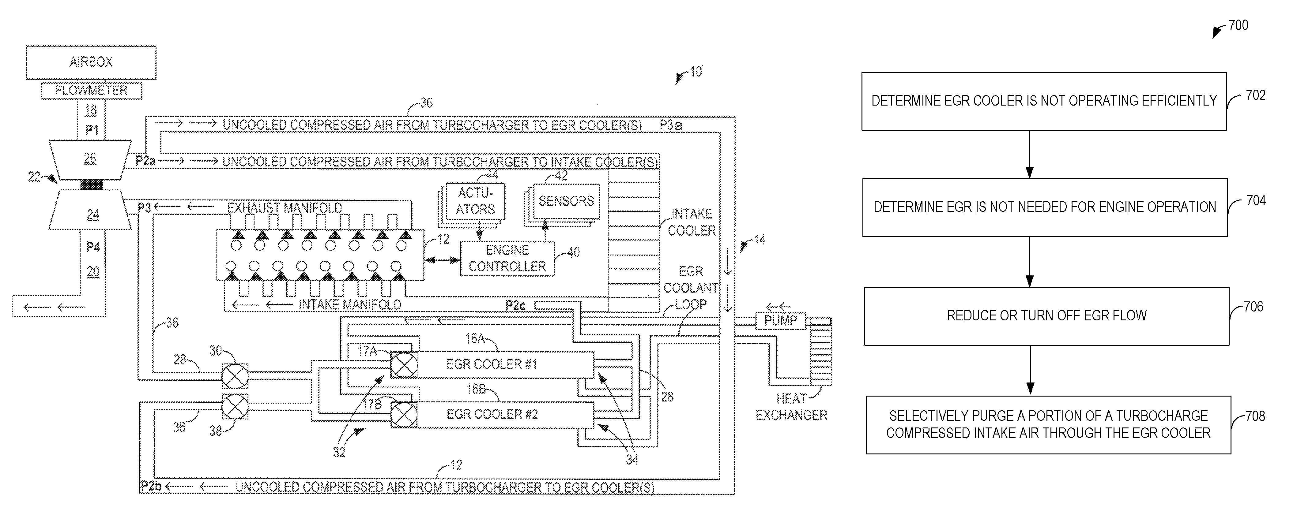
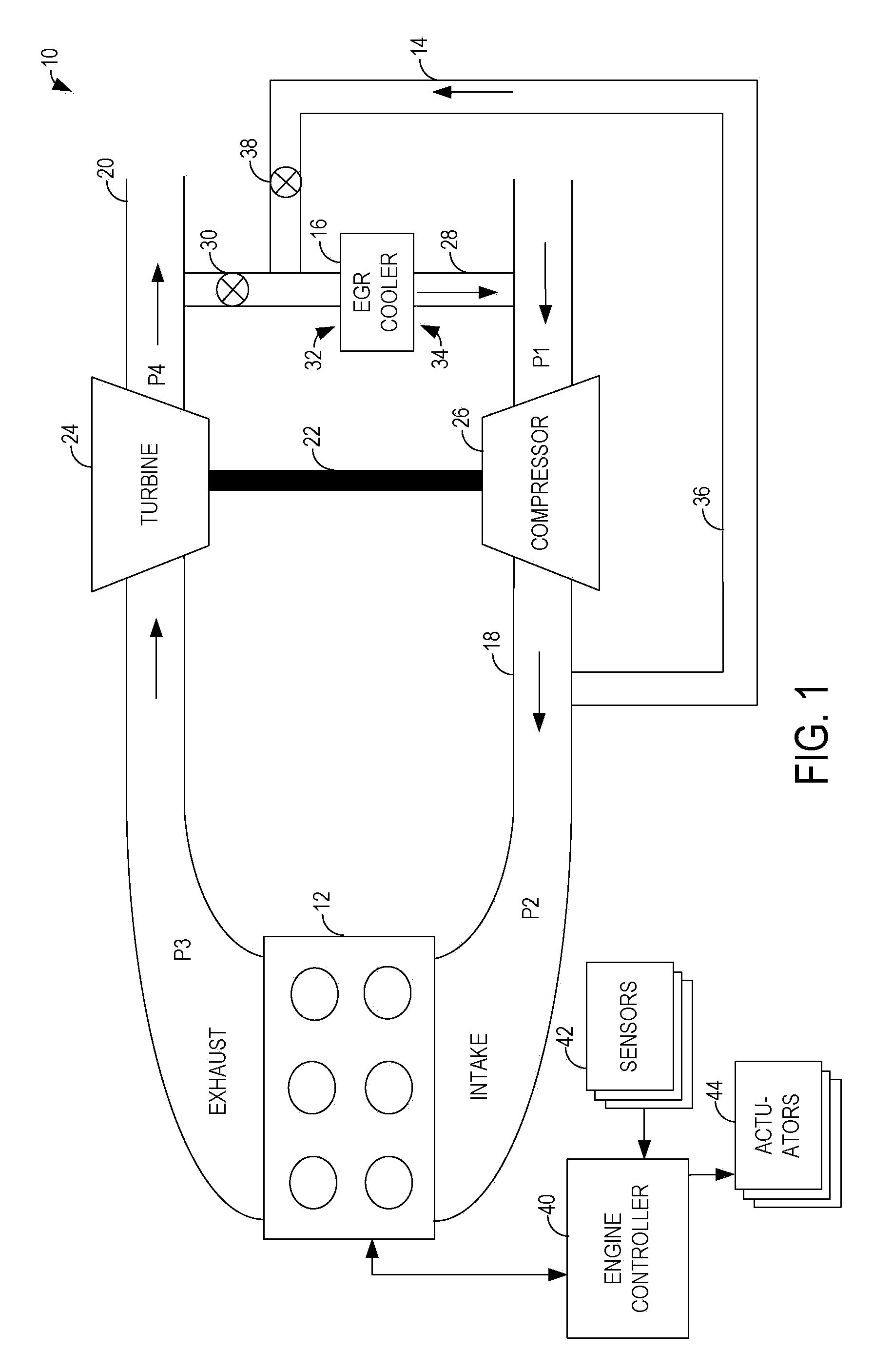
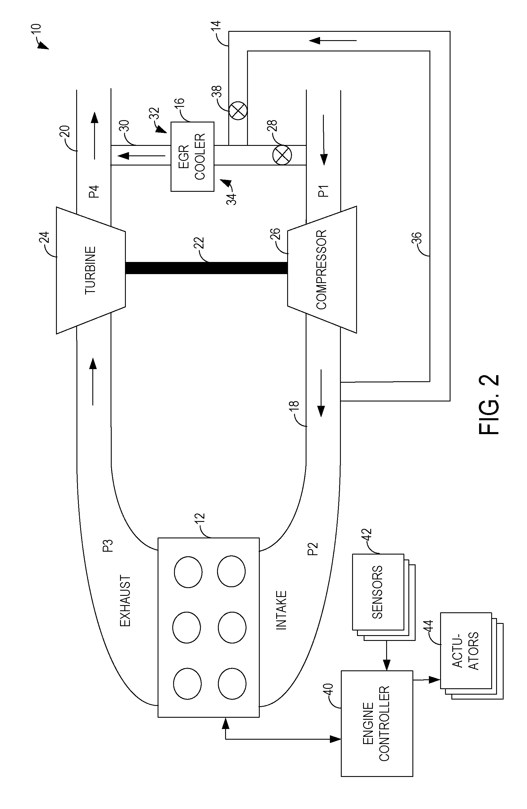
[0014]FIGS. 1-6 are schematic diagrams illustrating embodiments of an EGR system 10 of an internal combustion engine 12 that utilizes a compressed intake air delivery system 14 to delivery compressed air that is compressed by a turbocharger to remove soot particles deposited in an EGR cooler 16. The EGR system 10 illustrated in FIGS. 1 to 2 are low pressure EGR systems, while the EGR systems 10 illustrated in FIGS. 3 to 6 are high pressure EGR systems. For purpose of simplicity, similar parts are labeled similarly in FIGS. 1 to 6.

[0015]The internal combustion engine 12 may be coupled to an intake passage 18 and an exhaust passage 20. The engine 12 may include a turbocharger 22 having a turbine 24 and a compressor 26, where the turbine 24 may be coupled to the exhaust passage 20 and powered by exhaust gas flowing through the exhaust passage 20, and the compressor 24 may be coupled to the intake passage 18 for compressing intake air flowing through the intake passage 18. It should be ...


PUM


Abstract

Systems and methods for using compressed intake air that is free of soot particles to clean the EGR cooler of an internal combustion engine having a turbocharger are provided herein. One example system includes an EGR valve for selectively diverting a portion of exhaust gas through an EGR conduit to an intake side of the internal combustion engine. The EGR cooler is disposed in the EGR conduit. The compressed intake air delivery system is configured to selectively divert a portion of compressed intake air compressed by the turbocharger through the EGR cooler to remove soot particles deposited in the EGR cooler.

Description

BACKGROUND AND SUMMARY[0001]Exhaust gas recirculation is used to improve emission performance of diesel engines. Prior to being introduced into engine combustion chambers, the exhaust gas may be circulated through one or more EGR coolers. Due to the low temperature environment and flow characteristics of the EGR cooler, soot particles contained in the exhaust gas may be deposited onto walls of the EGR cooler to form a film of soot, often in a relatively short period of time, decreasing the heat transfer ability of the EGR cooler. As a result, the recirculated exhaust gas may not be effectively cooled and the ability of the recirculated exhaust gas to improve emission may be reduced.[0002]Various methods have been utilized to address the issue of soot deposition in EGR coolers. In some examples, particulate filters and oxidative catalysts have been used to remove soot particles upstream of the EGR coolers. However, the particulate filters and oxidative catalysts may take up significa...

Claims


Application Information

Patent Timeline
Patent Type & Authority Patents(United States)
IPC IPC(8): F02B33/44F02B29/04F02M25/07F01P7/14
CPCF02M25/0701F02M25/0732F02M25/0742F02B37/00F02M25/0707F02M25/0709F02M25/0731F02M25/0751Y02T10/121F02M26/05F02M26/06F02M26/50F02M26/28F02M26/24F02M26/36F02M26/44
Inventor PEARSON, GAVIN JAMES ROBERT
Owner FORD GLOBAL TECH LLC
Why Eureka
Try Eureka