Phase noise measurement system and method

Active Publication Date: 2012-08-21
ADVANCED TESTING TECH
View PDF39 Cites 30 Cited by
  • Summary
  • Abstract
  • Description
  • Claims
  • Application Information

AI Technical Summary

Benefits of technology

[0008]It is therefore an object of one or more embodiments of the present invention to provide a system, arrangement and method for quantifying, measuring and / or evaluating phase noise in a radar system and ideally, in the entire radar system. An exemplifying purpose of these measurements is to detect phase noise problems in an installed radar system that contribute to target and / or clutter resolution issues. The invention will measure phase noise and as a result of such measurements, aid in the isolation and replacement of components that are the source of excessive phase noise in radar systems.
[0009]It is another object of the invention to be able to quantify phase noise of a radar system after the radar system has been installed and placed into regular service, and used thereat, with a view toward enabling the radar system to be reliably used to its fullest extent and / or in accordance with its design parameters.
[0011]In addition, one or more embodiments of the invention relate to a phase noise test system for evaluating the noise floor of an entire radar system, potentially deployable at the system level and which is capable of making large system phase noise measurements and clutter suppression evaluation of airborne, shipboard and ground based radar systems. The test system uses one or more DRFM devices as part of a phase noise measurement system. As mentioned above, the DRFM device is used as a target / clutter generator to find radar system target detection problems associated with phase noise. The DRFM device is then used as a delay generator for measuring absolute and / or additive phase noise. The DRFM is capable of providing sufficient delay to perform additive phase noise measurements on a large radar system signal path. By measuring radar system signal paths in-situ, the system phase noise measurement provides a means for detecting and isolating phase noise problems that are impacting radar system performance.

Problems solved by technology

Phase noise in radar systems can inhibit target detection due to instabilities that affect a Moving Target Indicator (MTI) function of the radar.
Instabilities in the transmitted pulse, RF oscillators, receiver amplifiers and RF signal paths in a radar system can all be sources of phase noise.
The total phase noise of a radar system can cause targets to be lost against background clutter returns.
Surveillance radar systems use MTI processing to discern targets against clutter returns; however, excessive phase noise can impact clutter cancellation.
The phase noise impact on clutter cancellation causes targets to fall below the threshold of detection of the Constant False Alarm Rate (CFAR) of the radar system.
This unfortunately results in targets that are invisible to the surveillance system.
It is difficult to measure and quantify the phase noise present in a fully installed and integrated system on-board an aircraft or ship, or other vehicle or vessel.
Varying power levels, frequencies and long signal paths make measurement of phase noise using conventional techniques quite challenging.
It is unlikely, however, that once a component is installed in the radar system that any degradation in phase stability will be detected by ordinary system operation.
Over time, a radar operator may notice some difficulty in target detection, but unless a means of quantifying the total system phase noise is employed, the degradation will often go unchecked and the surveillance system could be compromised.
However, once a radar system is installed and placed into regular service, for example, on-board an aircraft, ship or other vehicle or vessel, the radar system phase noise is not quantified, nor is the impact of phase noise on target detection accurately measured.

Method used


Image

  • Phase noise measurement system and method
  • Phase noise measurement system and method
  • Phase noise measurement system and method

Examples


Embodiment Construction

[0021]DRFM Radar Target Sensitivity Evaluation:

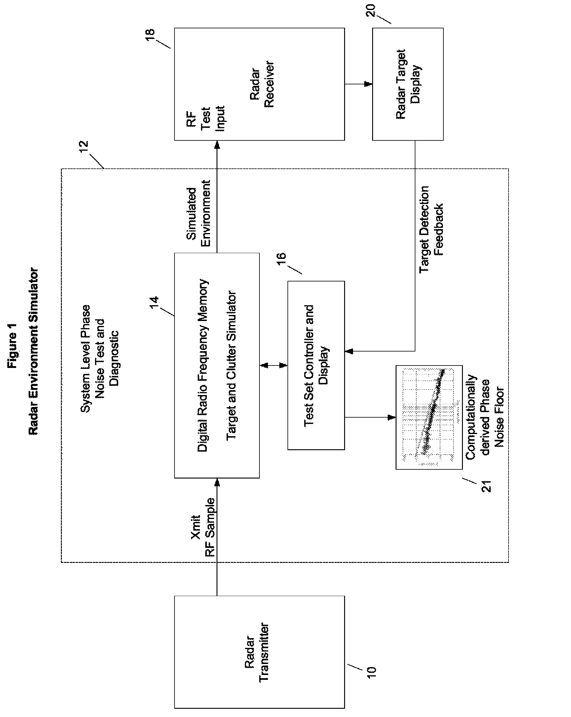
[0022]Referring to the accompanying drawings wherein like reference numerals refer to the same or similar elements, FIG. 1 illustrates the use of a Digital Radio Frequency Memory (DRFM) as a Radar Target Sensitivity Evaluator. The DRFM provide a means of simulating targets and / or clutter at various radar cross sections and velocities. In an exemplifying use, the DRFM is used to identify one or more target detection weaknesses by simulating targets of various velocities and clutter backgrounds, i.e., a plurality of different combinations of target velocity and clutter background. In these combinations, the target velocity may be constant as the clutter background changes from one simulation to the next, the target velocity may change while the clutter background remains the same from one simulation to the next or both the target velocity and clutter background may change from one simulation to the next. As each target velocity is tested,...


PUM


Abstract

System that measures absolute or additive phase noise includes a power divider for dividing an input RF signal, a local oscillator, two mixers, each arranged in a path of a respective signal component from the power divider and receiving input from the power divider and local oscillator, two digital radio frequency memories, each associated with a respective mixer and receiving an input signal therefrom, and a digital signal processor that receives signals from the digital radio frequency memories and outputs a digital data stream indicative of measured phase noise. For absolute phase noise measurement, phase noise of the input RF signal is provided. For additive phase noise measurement, a unit under test is arranged in one of the paths between the power divider and the mixer. The system may be interposed between a radar transmitter of a radar environment simulator and a radar receiver coupled to a radar target display.

Description

CROSS REFERENCE TO RELATED APPLICATION[0001]This application claims priority under 35 U.S.C. §119(e) of U.S. provisional patent application Ser. No. 61 / 473,886 filed Apr. 11, 2011, now expired, incorporated by reference herein.FIELD OF THE INVENTION[0002]The present invention relates generally to systems that measure noise present in radio frequency (RF) signals, and more specifically, to test equipment for use with radar systems components on-board aircraft and in laboratories. Even more particularly, the present invention relates to automatic test systems that measure and enable evaluation of phase noise in radar systems.[0003]The present invention also relates generally to methods for measuring noise present in electronic signals such as radio frequency (RF) signals, and more specifically, to noise measurement methods implemented in test equipment that test radar systems components on-board aircraft and in laboratories. Even more particularly, the present invention relates to met...

Claims


Application Information

Patent Timeline
IPC IPC(8): G01S13/00G01S7/40
CPCG01S7/4052G01S2007/4069G01S2007/4065G01S7/4065G01S7/4069
Inventor BAKER, JOHNLEVI, ELI
Owner ADVANCED TESTING TECH
Why Eureka
Try Eureka