Anti-vibration rubber device

a rubber device and anti-vibration technology, applied in the direction of shock absorbers, vibration dampers, non-rotating vibration suppression, etc., can solve the problems of cracks occurring cracks in the constricted portion, so as to achieve sufficient inhibition, prevent or inhibit effectively, and increase the resistance to gas permeability

Inactive Publication Date: 2013-01-03
SUMITOMO RIKO CO LTD
View PDF6 Cites 0 Cited by
  • Summary
  • Abstract
  • Description
  • Claims
  • Application Information

AI Technical Summary

Benefits of technology

The present invention provides an anti-vibration rubber device that prevents cracks from occurring in a high-temperature environment. This is achieved by covering and protecting the stress concentration portion of the constricted portion in the main rubber body with a rubber ring having higher resistance to gas permeability than the main rubber body. This prevents small cracks from occurring and effectively delays the occurrence of cracks. Additionally, the rubber ring is not tightly attached to the entire outer peripheral surface of the main rubber body, reducing the impact on the spring property of the main rubber body. The rubber ring is easily mounted on the constricted portion without the need for additional materials or work. This efficient and cost-effective anti-vibration rubber device provides stable performance in high-temperature environments without extra cost.

Problems solved by technology

In use of an anti-vibration rubber device having a main rubber portion provided with such a constricted portion for a long period of time, cracks may occur in the constricted portion.
In addition, in a case where such an anti-vibration rubber device is applied to an engine mount for a vehicle, for example, for a long period of time in a location where the temperature reaches 100° C. or higher, such as an engine compartment, cracks are more likely to occur significantly in the constricted portion.
It is considered that cracks occur in the constricted portion mainly because of oxidation of rubber that forms the main rubber portion.
Thus, it is considered that cracks occur significantly in use in a high-temperature environment, such as in an engine compartment.
Taking such measures may increase material cost due to change of a rubber material type or cause difficulty in achieving predetermined anti-vibration performance due to change of the shape of the main rubber portion.
In such a conventional anti-vibration device, however, the rubber membrane is bonded to the entire outer peripheral surface of the main rubber portion, thus considerably affecting a spring property of the main rubber portion.
In addition, extra cost and work are required to bond the rubber membrane to the main rubber portion.
Furthermore, the rubber membrane, which is simply heat resistant, cannot prevent the outer peripheral surface of the main rubber portion from being in contact with oxygen that permeates the rubber membrane, thus being insufficient in preventing oxidation of the main rubber portion.

Method used


Image

  • Anti-vibration rubber device
  • Anti-vibration rubber device
  • Anti-vibration rubber device

Examples


Embodiment Construction

[0025]In order to clarify the present invention further specifically, a configuration of the present invention is described below with reference to the drawings.

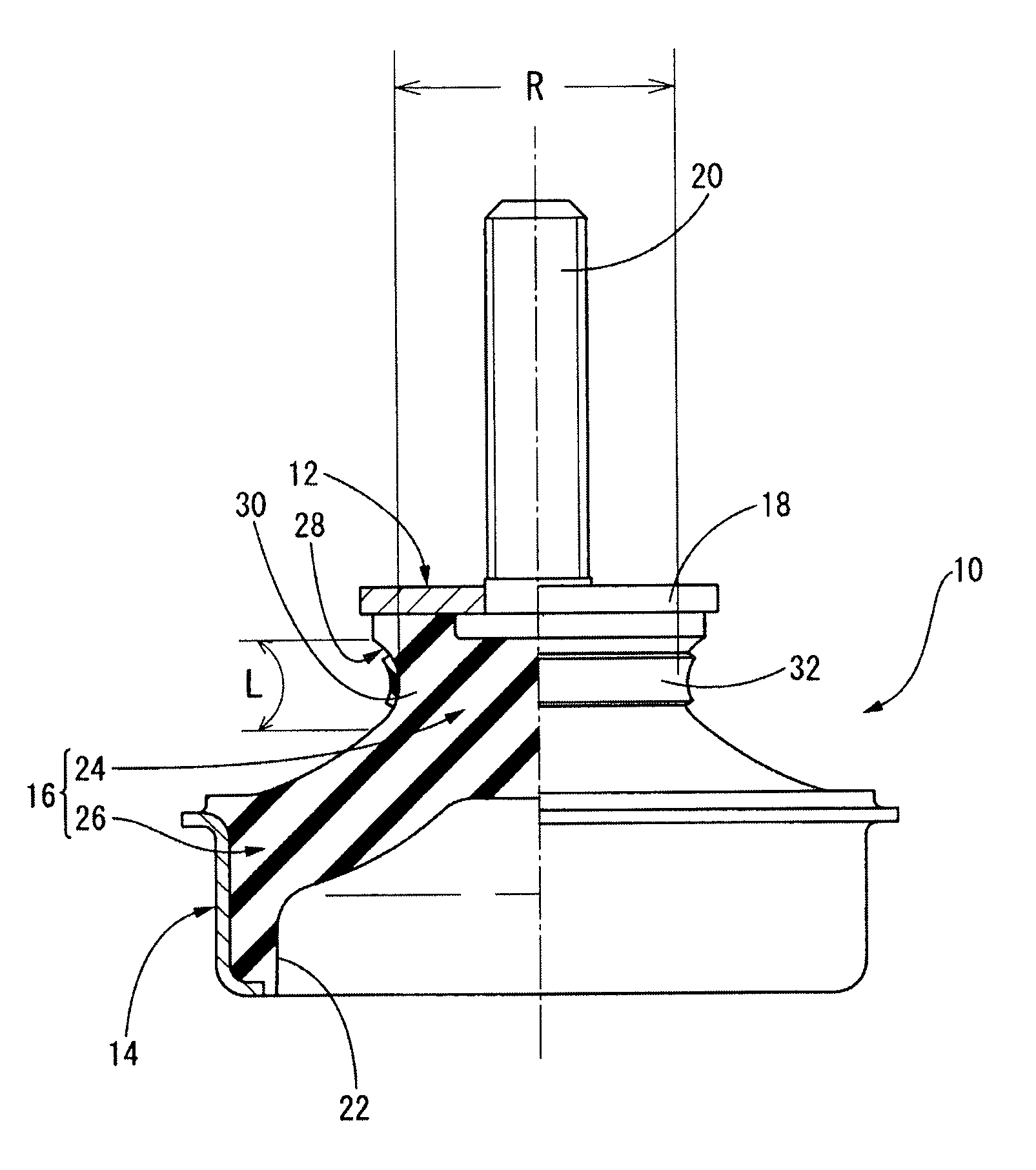
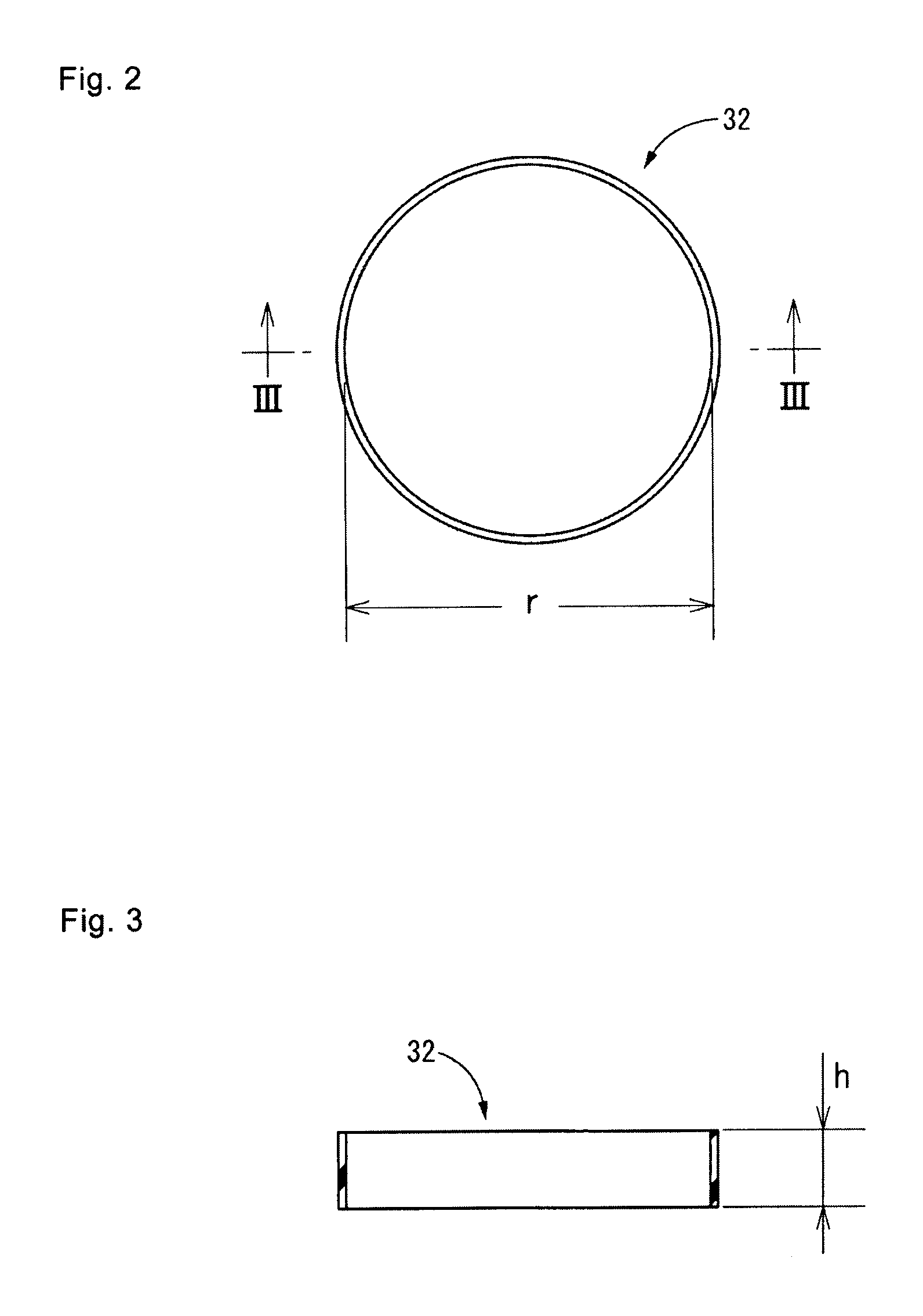
[0026]FIG. 1 is a half view illustrating an engine mount for an automobile, which is an anti-vibration rubber device according to an embodiment of the present invention. As shown in FIG. 1, an engine mount 10 of the present embodiment has a structure in which a first attachment fitting 12 as a first attachment member and a second attachment fitting 14 disposed distant therefrom as a second attachment member are integrally connected by a main rubber portion 16 provided between the first attachment fitting 12 and the second attachment fitting 14. Of the engine mount 10, the first attachment fitting 12 is attached to a power unit and the second attachment fitting 14 to a vehicle body (not shown in the drawing). Thus, the power unit is supported on the vehicle body and is prevented from vibrating in a state where the engine moun...


PUM


Abstract

An anti-vibration rubber device is capable of advantageously preventing cracks from occurring in a constricted portion because of a long time use in a high-temperature environment. A rubber ring having higher resistance to gas permeability than a main rubber portion is externally inserted in a tension-deformed state to a stress concentration portion of a constricted portion in the main rubber portion that connects a first attachment member and a second attachment member. Due to a restoring force from the tension-deformed state, the rubber ring is tightly attached without being bonded to an outer peripheral surface of the stress concentration portion.

Description

CLAIM OF PRIORITY[0001]This application is a continuation of PCT / JP2011 / 075797 filed Nov. 9, 2011, and claims the priority benefit of Japanese Application No. 2010-273786, filed Dec. 8, 2010, the contents of which is expressly incorporated by reference in its entirety.TECHNICAL FIELD[0002]The present invention relates to an anti-vibration device, particularly an anti-vibration device suitable for an engine mount for a vehicle, such as an automobile.BACKGROUND ART[0003]A type of conventional anti-vibration connector or anti-vibration support provided between two members included in a vibration transmission system is an anti-vibration rubber device having a structure in which a first attachment member and a second attachment member to be attached to the respective two members are connected by a main rubber portion composed of a rubber elastic body having at least one of a block portion and a tubular portion provided between the attachment members. Such an anti-vibration rubber device ...

Claims


Application Information

Patent Timeline
Patent Type & Authority Applications(United States)
IPC IPC(8): F16F15/08F16F7/00
CPCF16F1/3713
Inventor ISHIKAWA, RYOTAOGAWA, YUICHISHIMIZU, YORISHIGE
Owner SUMITOMO RIKO CO LTD
Why Eureka
Try Eureka