
Detection values determination system

a detection value and determination system technology, applied in the field of detection value determination system, can solve the problems of reduced detection value quality, reduced quality of detection value determination, and incomplete loss of original photon energy information, etc., and achieve the effect of improving quality

Active Publication Date: 2021-05-11
KONINKLJIJKE PHILIPS NV
View PDF9 Cites 0 Cited by
  • Summary
  • Abstract
  • Description
  • Claims
  • Application Information

AI Technical Summary

Benefits of technology

The present invention provides a detection values determination system and method with improved quality. The system uses an anti-charge-sharing grid that only affects detection pixels within a certain cluster, resulting in a smaller area of detection compared to traditional systems. The system also includes a detection values determination unit that can correct for charge sharing between detection pixels of a same cluster, with relatively low technical effort. The system can also prioritize detection pixels within a cluster to improve the quality of the determined charge-sharing-corrected detection values. Overall, the system provides higher quality detection values with reduced effort.

Problems solved by technology

The spectral performance of the detection values determination system used in a photon counting computed tomography system is often limited by a so called charge-sharing effect, wherein charge, which is caused by a single photon, is shared between neighboring detection pixels of the detection values determination system accompanied by a complete loss of the energy information of the original photon.
However, if this is not the case, charge sharing occurs, resulting in a reduced quality of the determined detection values.
This covering of a part of the detection surface has the disadvantage that it leads to a significant loss in detective quantum efficiency (DQE) such that the quality of the determined detection values is still reduced.

Method used


Image

  • Detection values determination system
  • Detection values determination system
  • Detection values determination system

Examples


Embodiment Construction

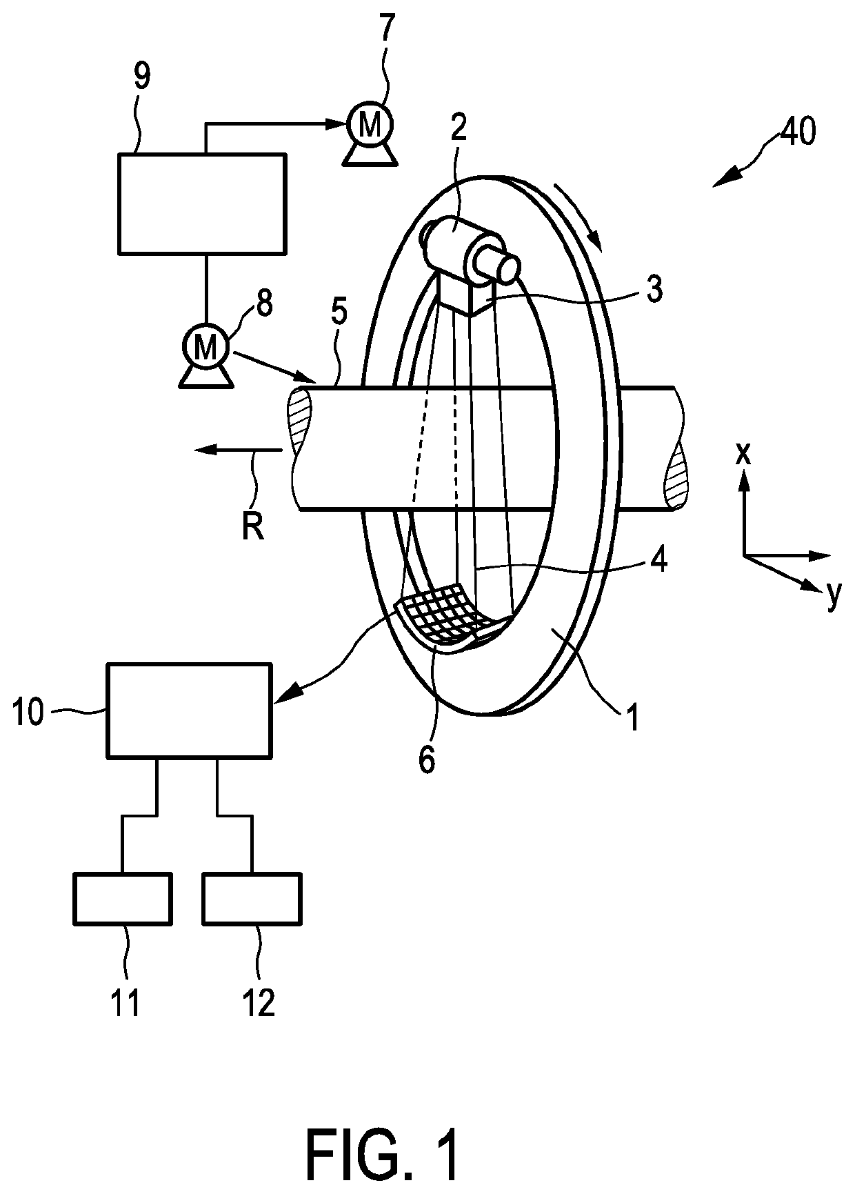
[0042]FIG. 1 shows schematically and exemplarily an embodiment of an imaging system for generating an image of an object. In this embodiment the imaging system is a computed tomography system 40. The computed tomography system 40 comprises a gantry 1 which is capable of rotation about a rotational axis R which extends parallel to a z direction. A radiation source 2, which in this embodiment is an x-ray tube, is mounted on the gantry 1 and is provided with a collimator 3 which forms a conical radiation beam 4 from the radiation generated by the radiation source 2. The radiation traverses the object being, in this embodiment, a human patient within a cylindrical examination zone 5. After having traversed the examination zone 5 and hence the patient the radiation beam 4 is incident on a detection device 6 which comprises a two-dimensional detection surface. Also the detection device 6 is mounted on the gantry 1.

[0043]The computed tomography system 40 comprises two motors 7, 8. The gant...


PUM


Abstract

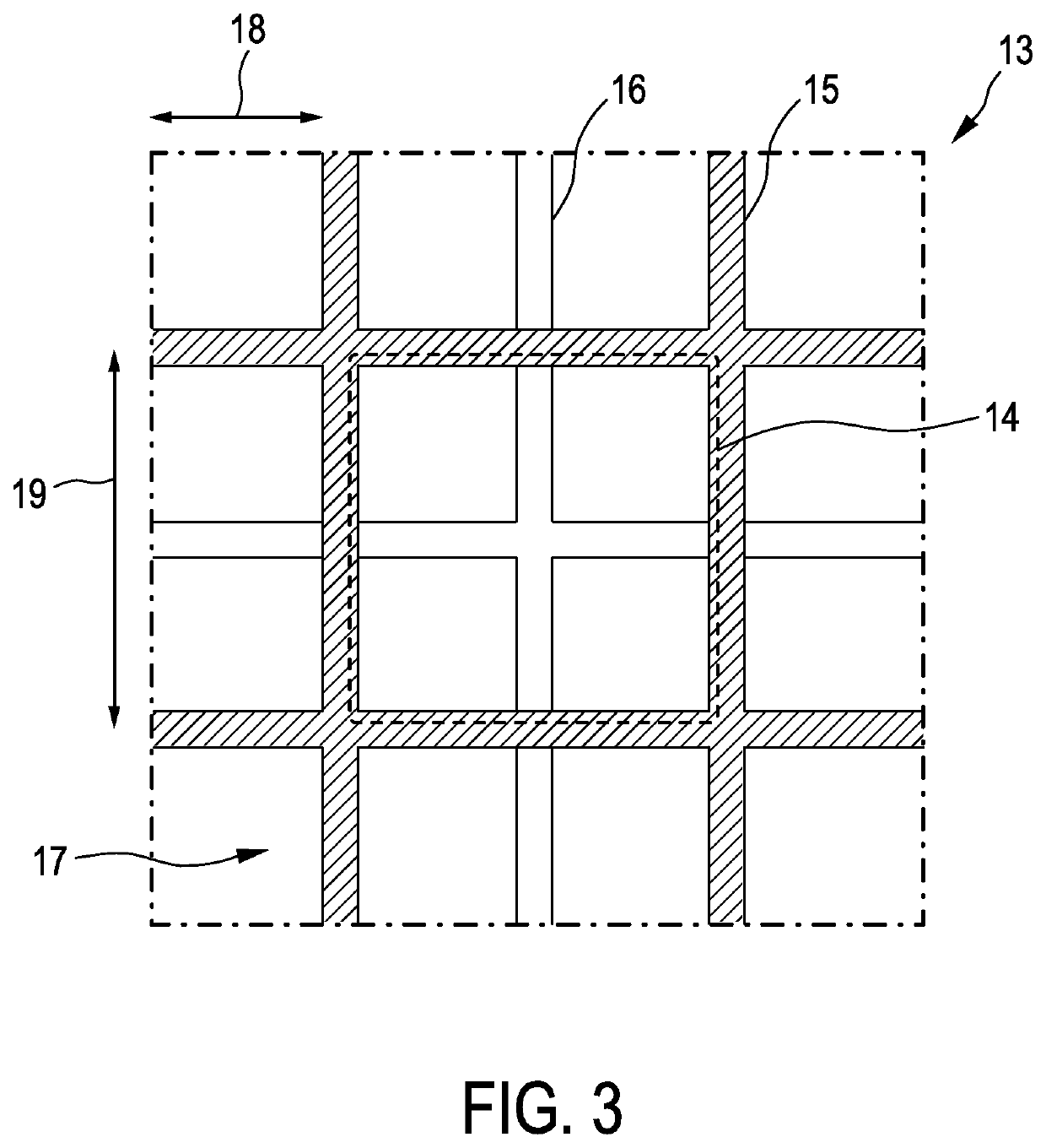
The invention relates to a detection values determination system, especially for photon-counting CT scanners, comprising a detection pulse providing unit for providing detection pulses for an array of detection pixels 17, which is provided with an anti-charge-sharing grid 15 for suppressing charge sharing between different clusters 14 of the detection pixels, wherein the detection pulses are indicative of the energy of photons incident on the detection pixels. Charge-sharing-corrected detection values are determined based on the provided detection pulses, wherein for determining a charge-sharing-corrected detection value for a detection pixel of a cluster only detection pixels of the same cluster are considered. This allows for a relatively high detective quantum efficiency, wherein the technical efforts for providing the charge sharing correction can be relatively low.

Description

CROSS REFERENCE TO RELATED APPLICATIONS[0001]This application is the U.S. National Phase application under 35 U.S.C. § 371 of International Application No. PCT / EP2016 / 078216, filed Nov. 20, 2016, published as WO 2017 / 085304 on May 26, 2017, which claims the benefit of European Patent Application Number 15195557.2 on Nov. 20, 2015. These applications are hereby incorporated by reference herein.FIELD OF THE INVENTION[0002]The invention relates to a detection values determination system and method for determining charge-sharing-corrected detection values to be used by an imaging system for generating an image of an object. The invention further relates to the imaging system and a computer program for controlling the detection values determination system.BACKGROUND OF THE INVENTION[0003]Detection values determination systems are used, for instance, in photon counting computed tomography systems. The spectral performance of the detection values determination system used in a photon count...

Claims


Application Information

Patent Timeline
Patent Type & Authority Patents(United States)
IPC IPC(8): G01T1/29
CPCG01T1/2928
Inventor ROESSL, EWALDSTEADMAN BOOKER, ROGER
Owner KONINKLJIJKE PHILIPS NV
Learn More