Rotary electric machine with air gaps configured to cancel torque pulsations
a technology of torque pulsation and rotary electric machines, which is applied in the direction of magnetic circuit rotating parts, electric devices, magnetic circuit shapes/forms/construction, etc., can solve the problems of noise or vibration, deterioration of ride quality, and inability to appropriately reduce the inherent cogging torque, so as to reduce the torque pulsation caused in relation to the stator current supplied to the stator winding
- Summary
- Abstract
- Description
- Claims
- Application Information
AI Technical Summary
Benefits of technology
Problems solved by technology
Method used
Image
Examples
first embodiment
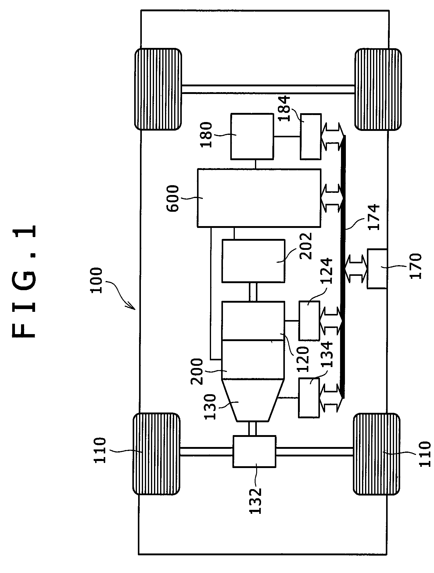
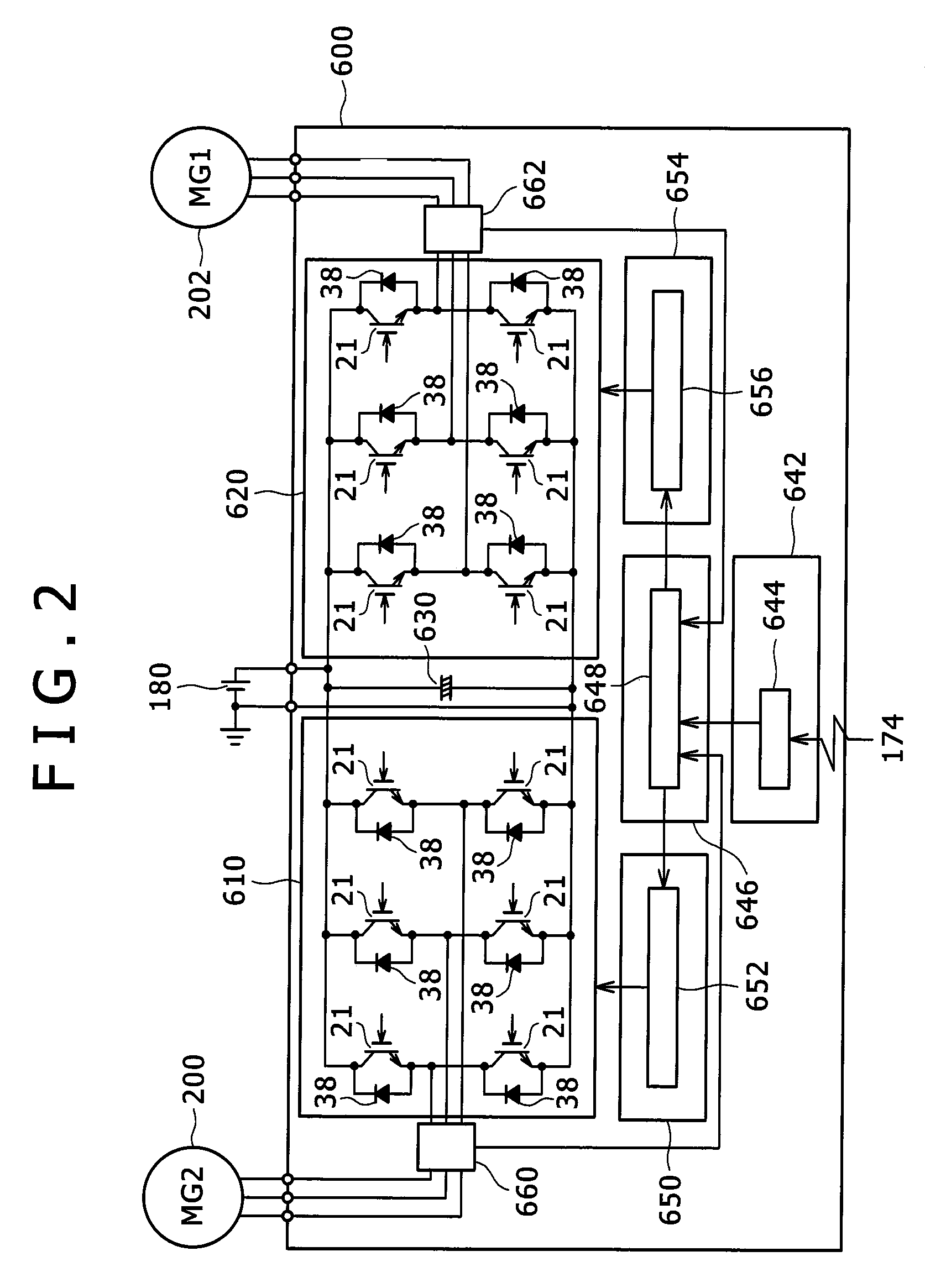
[0087]FIG. 1 is a diagram showing a schematic construction of a hybrid electric vehicle equipped with the rotary electric machine according to one embodiment of the invention. A vehicle 100 is equipped with an engine 120, a first rotary electric machine 200, a second rotary electric machine 202, and a battery 180. The battery 180 supplies direct-current power to a power converter (inverter) 600 for driving the rotary electric machines 200 and 202 when driving forces for the machines 200 and 202 are necessary. The power converter 600 converts the direct-current power into alternating-current power, and respectively supplies the converted alternating-current power to the rotary electric machines 200 and 202. In regeneration traveling, the rotary electric machines 200 and 202 generate alternating-current power based on kinetic energy of the vehicle to supply the power to the power converter 600. The power converter 600 converts the alternating-current power into direct-current power to...
second embodiment
[0159]FIGS. 22 to 24 are diagrams for explaining the second embodiment of the invention.
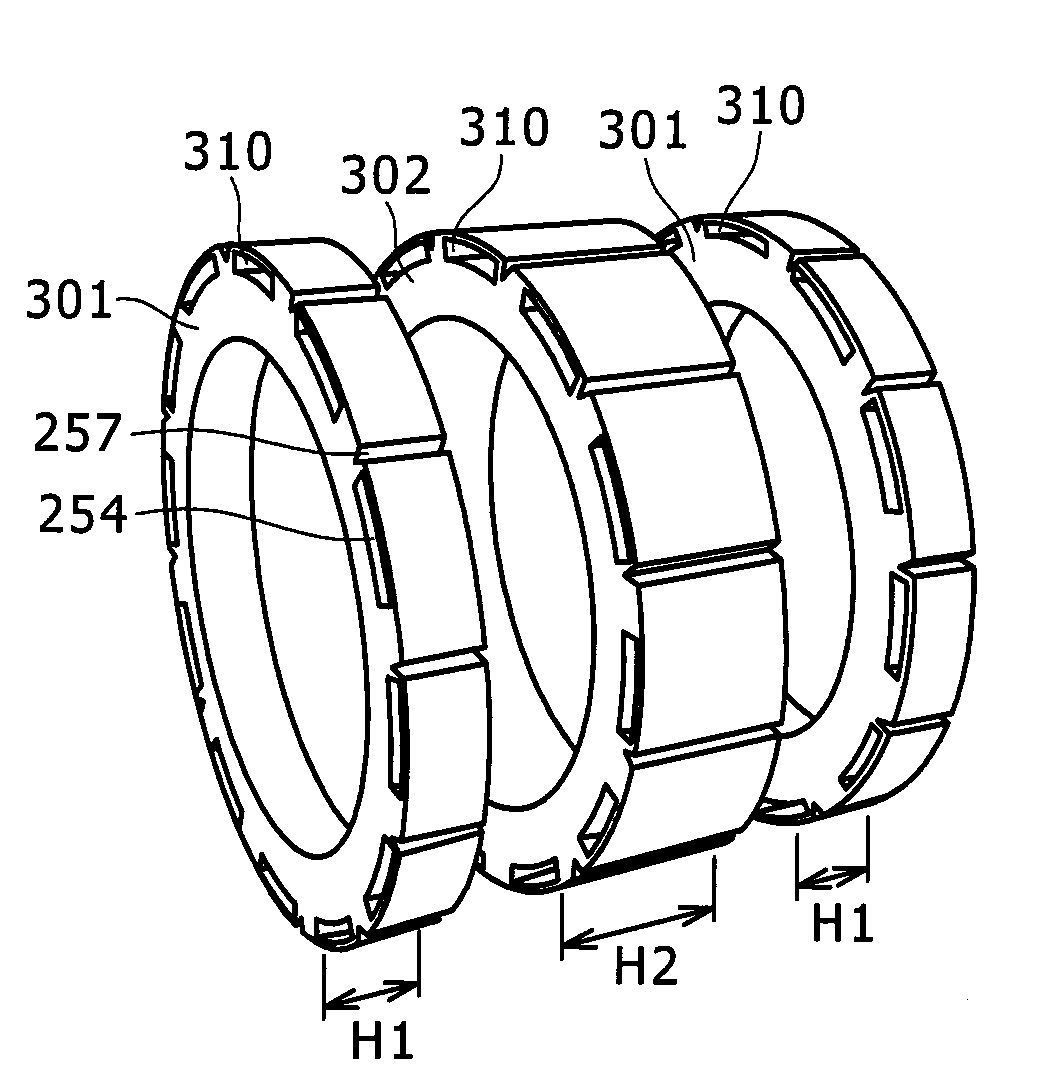
[0160]FIG. 22A is a sectional view of the rotor 250 corresponding to the section taken along the line A-A shown in FIG. 6A, and FIG. 22B is a sectional view of the rotor 250 corresponding to the section taken along the line B-B shown in FIG. 6B. That is, also in the second embodiment, the rotor core 252 is constructed of three cores as shown in FIG. 5. FIG. 22A shows the section of the core 301, and the FIG. 22B shows the section of the core 302. In the above example shown in FIG. 6, the magnetic air gaps 258 are formed as the slot on the surface of the rotor core 252. In the second embodiment, the air gaps 258 are formed inside the rotor core 252.
[0161]The sectional shape of the permanent magnets 245 (254a, 254b) is rectangular, and the magnetic air gap 258 is provided so as to be in contact with one side of the field pole made by the permanent magnets 245 (254a, 254b). In FIG. 22A, a magnetic a...
third embodiment
[0169]FIG. 25 shows a rotor 250 according to a third embodiment. FIG. 25A is a sectional view corresponding to the sectional view taken along the line A-A shown in FIG. 6A, and FIG. 25B is a sectional view corresponding to the sectional view taken along the line B-B shown in FIG. 6B. In the example shown in FIG. 25, two kinds of magnetic air gaps per one pole are provided. That is, a pair of magnetic air gaps 251 are also provided in the core on the outer peripheral side of the magnet, in addition to the magnetic air gaps 258 in the auxiliary salient pole 259. The magnetic air gaps 251 are symmetrically provided with respect to the d axis passing through the center of the permanent magnet. The magnetic air gaps 251 may be provided asymmetrically. The magnetic air gap 251 is mainly provided for reducing the cogging torque, and thus is disposed in the core on the outer peripheral side of the magnet through which the magnet flux passes. Such an arrangement can respectively reduce the p...
PUM
 Abstract
Description
Claims
Application Information
 - R&D
- Intellectual Property
- Life Sciences
- Materials
- Tech Scout
- Unparalleled Data Quality
- Higher Quality Content
- 60% Fewer Hallucinations
Browse by: Latest US Patents, China's latest patents, Technical Efficacy Thesaurus, Application Domain, Technology Topic, Popular Technical Reports.
© 2025 PatSnap. All rights reserved.Legal|Privacy policy|Modern Slavery Act Transparency Statement|Sitemap|About US| Contact US: help@patsnap.com


