
Power Conversion Device

a power conversion device and power technology, applied in the direction of motor/generator/converter stopper, electric generator control, pulse manipulation, etc., can solve the problems of power conversion device mounted to a vehicle subjected to a higher temperature environment, etc., to achieve the effect of reducing torque pulsation and switching loss

Inactive Publication Date: 2011-02-03
HITACHI AUTOMOTIVE SYST LTD
View PDF10 Cites 23 Cited by
  • Summary
  • Abstract
  • Description
  • Claims
  • Application Information

AI Technical Summary

Benefits of technology

[0026]With the power conversion device according to the present invention, it is possible to reduce torque pulsation and switching losses.

Problems solved by technology

Due to this, there is a tendency for the amount of power to be converted by the power conversion device to become greater.
Furthermore, a power conversion device that is mounted to a vehicle is subjected to a higher temperature environment, as compared with a power conversion device that is mounted to a typical industrial machine that is installed in a workplace.
Two reasons for generation of heat in the switching devices are steady loss that takes place even while the switching devices are in the continuous state, and switching loss that takes place when the switching devices change between the discontinuous state and the continuous state.
In order to reduce the switching loss further, it is necessary to lower the carrier frequency that determines the switching frequency, but when the carrier frequency is decreased the current pulsation increases, and along with this the torque pulsation of the motor and the noise that it generates become greater.
However, sometimes it becomes difficult to reduce the torque pulsation as desired when the superimposed harmonic component and the carrier frequency approach one another, and on the contrary there is a possibility that the torque pulsation may increase.

Method used


Image

  • Power Conversion Device
  • Power Conversion Device
  • Power Conversion Device

Examples


Embodiment Construction

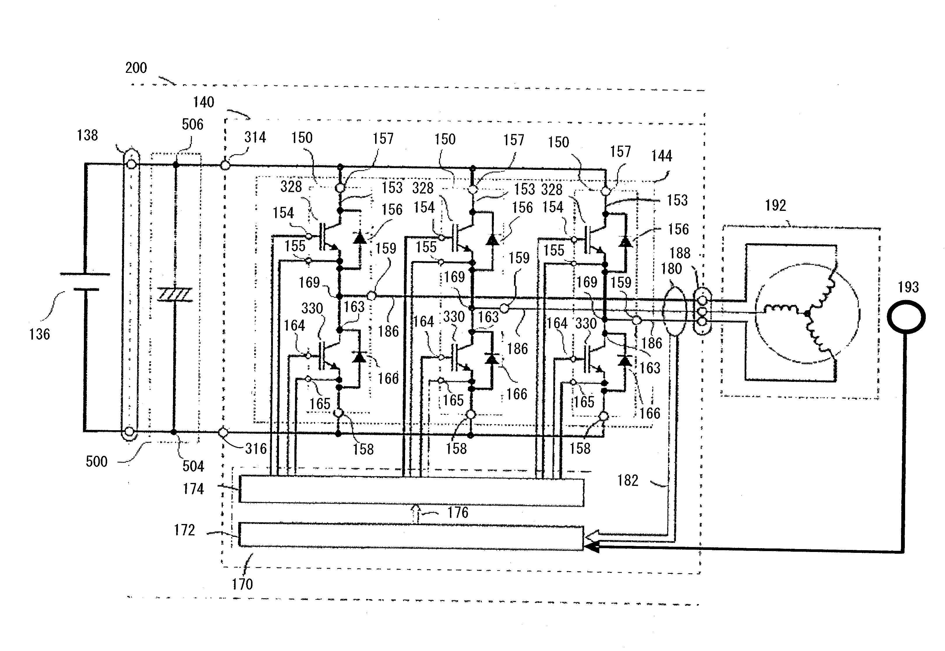
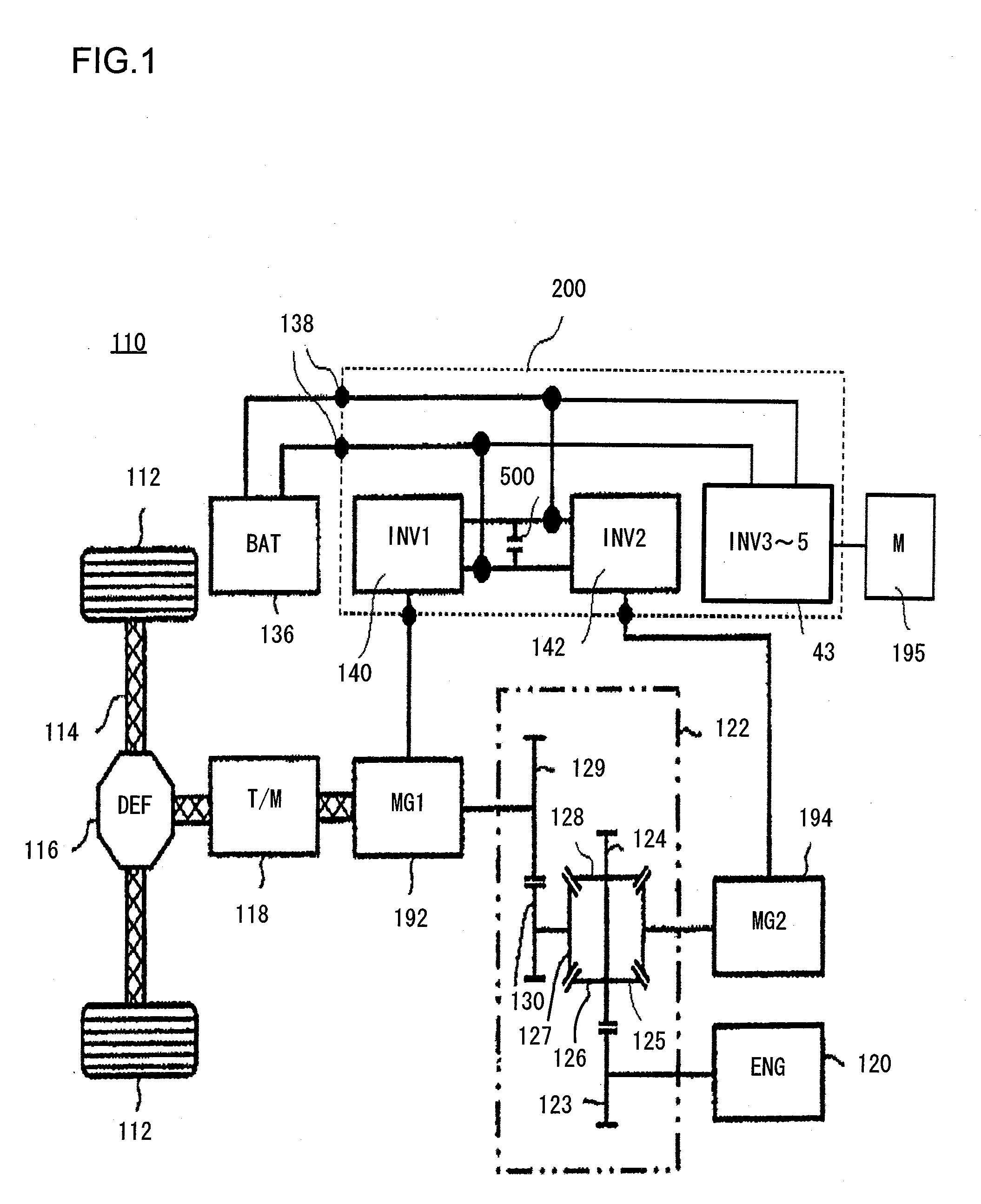
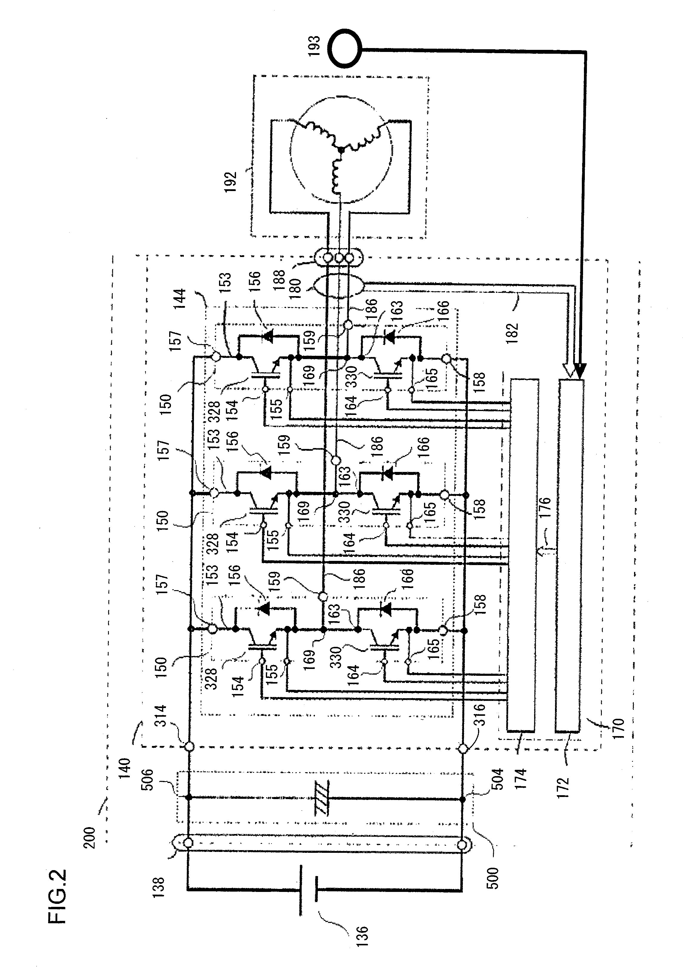
[0042]The power conversion devices according to embodiments of the present invention will now be described with reference to the drawings. The power conversion device of the present invention can be applied to a hybrid electric vehicle, or to a pure electric vehicle. However, as a representative example, the control structure when a power conversion device according to an embodiment of the present invention is applied to a hybrid electric vehicle, and the circuit structure of that power conversion device, will be explained with reference to FIGS. 1 and 2. FIG. 1 is a diagram showing the control block structure of this hybrid electric vehicle.

[0043]This power conversion device according to an embodiment of the present invention will now be explained by describing an example in which it is used as an onboard power conversion device in an onboard electrical system that is mounted to an automobile, and in particular in an onboard electrical system for driving a vehicle, i.e. when it is ...


PUM


Abstract

A power conversion device comprises a power conversion unit of a three phase full bridge type including upper arm switching devices and lower arm switching devices, and a controller that outputs drive signals to these switching devices. This power conversion device forms alternately a first interval in which the upper arm switching devices and the lower arm switching devices are switched to ON for different phases, and a second interval in which, for all phases, either the upper arm switching devices or the lower arm switching devices are switched to ON, according to electrical angle.

Description

INCORPORATION BY REFERENCE[0001]The disclosure of the following priority application is herein incorporated by reference: Japanese Patent Application No. 2009-178118 filed Jul. 30, 2009BACKGROUND OF THE INVENTION[0002]1. Field of the Invention[0003]The present invention relates to a power conversion device that converts DC power to AC power, or AC power to DC power.[0004]2. Description of Related Art[0005]In recent years, various types of environmentally-sensitive automobiles such as electric vehicles and hybrid electric vehicles employing an electric motor as a power source have become widespread. The main characteristic of such an environmentally sensitive automobile is that it is equipped with a battery, and that its wheels are driven by torque generated by a motor that utilizes this battery as a source of power. Generally an AC electric motor such as a permanent magnet synchronous electric motor or the like is used as this driving electric motor, since this makes it possible to ...

Claims


Application Information

Patent Timeline
IPC IPC(8): H02P27/06H02M7/48H02P21/00H02P21/05H02P21/22H02P23/04H02P23/16H02P27/08
CPCB60L11/1803B60L15/06B60L15/20B60L2210/20Y02T10/7275Y02T10/7005Y02T10/725B60L2200/26Y02T10/644B60L15/025B60L15/08B60L2210/42B60L2220/12B60L2220/14B60L2240/421B60L2240/423B60L2270/142B60L50/51H02M1/12H02M1/44H02M7/53871H02M7/5395H02P6/085H02P6/10H02P27/085H02P29/50H02M1/0054Y02T10/64Y02T10/70Y02T10/72Y02T10/92
Inventor FURUKAWA, KIMIHISAMIYAZAKI, HIDEKIYOSHIHARA, SHIGEYUKITAKAMUNE, YUICHIRO
Owner HITACHI AUTOMOTIVE SYST LTD
Learn More