Perpendicular magnetic recording head with bottom shield layer

a magnetic recording head and bottom shield technology, applied in the field of perpendicular magnetic recording heads, can solve the problems of deteriorating total recording performance, extremely small recording magnetic field, leakage magnetic flux, etc., and achieve the effect of reducing the thickness, and reducing the amount of leakage magnetic flux

Inactive Publication Date: 2012-08-14
TDK CORPARATION
View PDF21 Cites 5 Cited by
  • Summary
  • Abstract
  • Description
  • Claims
  • Application Information

AI Technical Summary

Benefits of technology

[0011]It is an object of the present invention to provide a perpendicular magnetic recording head which can suppress side fringing at the time of skewing and favorably keep both of the recording magnetic field intensity and recording magnetic field gradient.
[0012]The present invention is achieved by focusing attention on the fact that, when a shield layer is not provided on the trailing edge side of the main magnetic pole layer but partly on the leading edge side thereof, leakage magnetic fluxes occulting on the leading edge side are absorbed by the shield layer, so that side fringing at the time of skewing can be suppressed, while magnetic fluxes transmitted to the trailing edge side are not absorbed, whereby the recording magnetic field intensity applied to the recording medium can be restrained from decreasing.
[0014]Preferably, the bottom shield layer has a thickness of more than 90 nm. As the bottom shield layer has a greater thickness, it is harder to cause magnetic saturation even when absorbing magnetic fluxes leaking from the leading edge of the magnetic pole part of the main magnetic pole layer and can absorb a larger amount of leakage magnetic fluxes.
[0015]Preferably, the bottom shield layer has both ends in the track width direction extending from both side face positions in the track width direction of the magnetic pole part of the main magnetic pole layer. This mode allows the bottom shield layer to securely absorb magnetic fluxes leaking from the leading edge of the magnetic pole part.
[0016]The present invention provides a perpendicular magnetic recording head in which the bottom shield layer absorbs leakage magnetic fluxes from the leading edge of the magnetic pole part of the main magnetic pole layer without absorbing recording magnetic fluxes directed from the trailing edge side to the recording medium, so as to suppress side fringing at the time of skewing, thereby improving the recording magnetic field gradient and being able to favorably keep the improved recording magnetic field gradient.

Problems solved by technology

When the shield layer is provided like a flat film surrounding the main magnetic pole layer as in the Japanese Patent Application Laid-Open Nos. 2005-92929, 2005-190518 and 2005-310363, however, not only leakage magnetic fluxes from sides of the main magnetic pole layer but also recording magnetic fluxes applied from the main magnetic pole layer to the recording medium are absorbed by the shield layer, whereby the recording magnetic field becomes extremely small.
When the recording magnetic field intensity becomes extremely small as such, recording actions cannot be performed for recording media having a high coercively, whereby the total recording performance will deteriorate even if the recording magnetic field gradient improves.

Method used


Image

  • Perpendicular magnetic recording head with bottom shield layer
  • Perpendicular magnetic recording head with bottom shield layer
  • Perpendicular magnetic recording head with bottom shield layer

Examples


Embodiment Construction

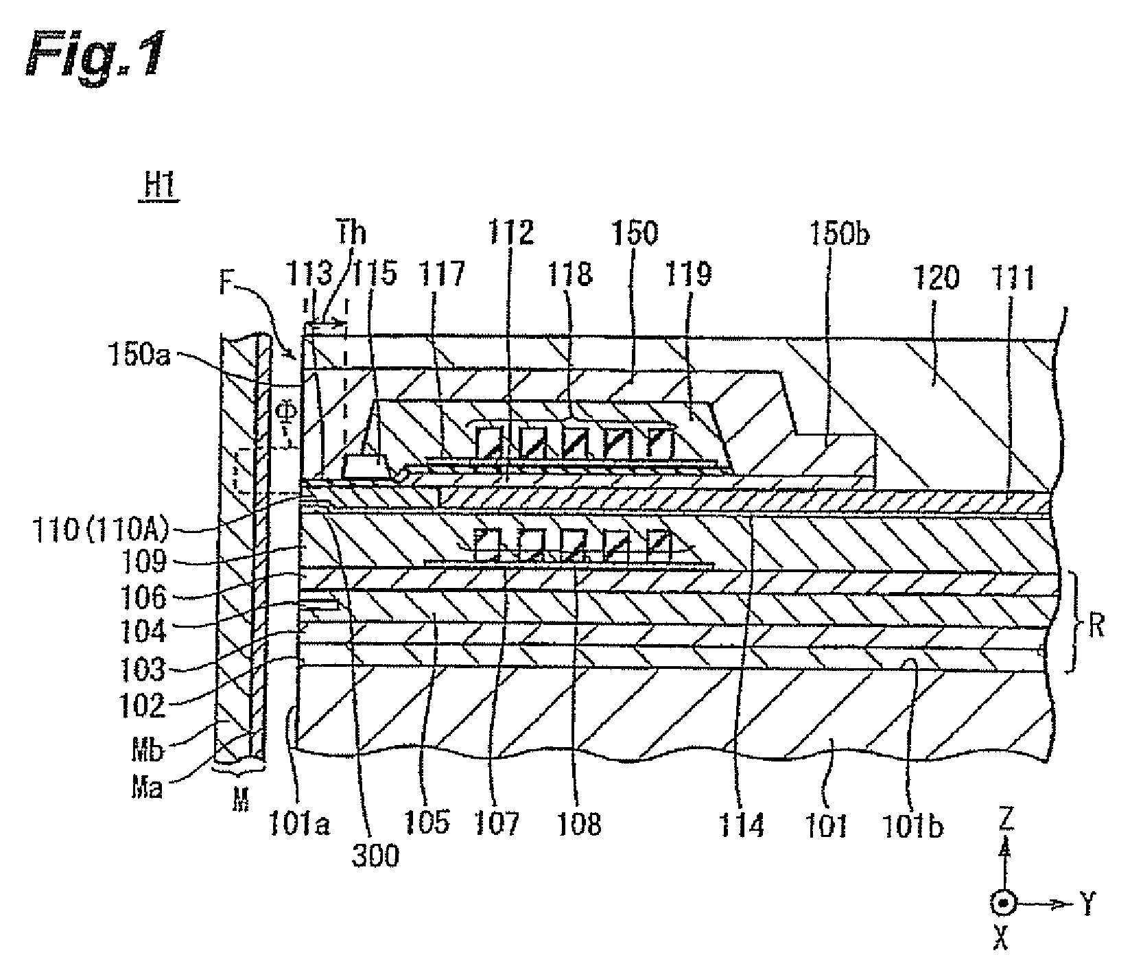
[0025]In the following, the present invention will be explained with reference to the drawings. In each drawing, X, Y, and Z directions are defined by the track width direction, the height direction, and the laminating direction (thickness direction) of layers constituting a perpendicular magnetic recording head, respectively.

[0026]FIGS. 1 to 5 show the perpendicular magnetic recording head H in accordance with an embodiment of the present invention.

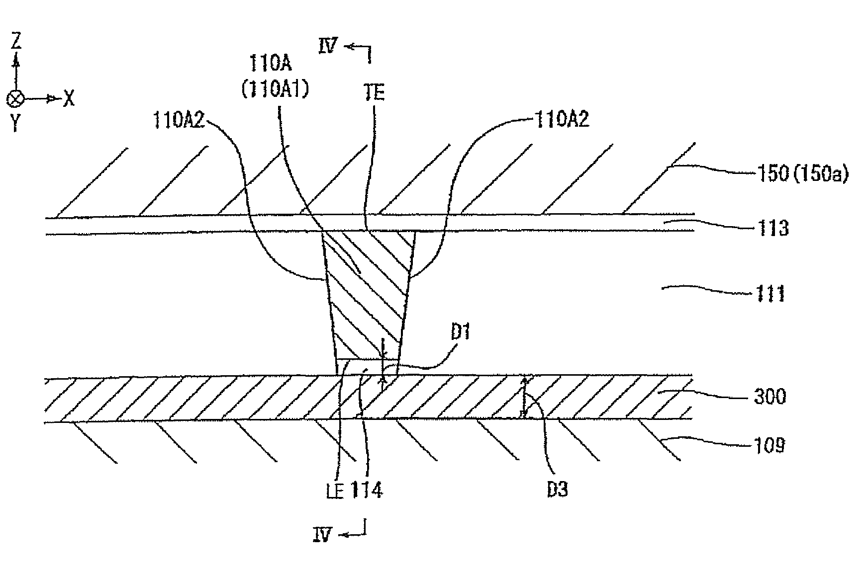
[0027]FIG. 1 is a vertical sectional view showing the overall structure of the perpendicular magnetic recording head H. The perpendicular magnetic recording head H provides a recording medium M with a recording magnetic flux Φ perpendicular thereto, thereby perpendicularly magnetizing a hard film Ma of the recording medium M. The recording medium M has the hard film Ma with a higher remanent magnetization on the medium surface side and a soft film Mb with a higher magnetic permeability on the inner side of the hard film Ma. The recording...


PUM

PropertyMeasurementUnit
thicknessaaaaaaaaaa
thicknessaaaaaaaaaa
thicknessaaaaaaaaaa

Abstract

In a perpendicular magnetic recording head in which a magnetic pole part of a main magnetic pole layer exposed at a medium-opposing surface exhibits a trapezoidal form narrower at a leading edge than at a trailing edge on the return yoke layer side, a bottom shield layer made of a soft magnetic material is provided below the leading edge of the magnetic pole part of the main magnetic pole layer in the track width direction while interposing a nonmagnetic material layer therebetween. The gap between the bottom shield layer and the leading edge of the magnetic pole part is set to less than 60 nm.

Description

BACKGROUND OF THE INVENTION[0001]1. Field of the Invention[0002]The present invention relates to a perpendicular magnetic recording head which is driven with a skew angle and performs a recording action by applying a recording magnetic-field perpendicularly to a recording medium plane.[0003]2. Related Background Art[0004]As is well-known, a perpendicular magnetic recording head includes a main magnetic pole layer and a return yoke layer which have front end faces exposed at a surface opposing a recording medium (medium-opposing surface) and are magnetically coupled to each other on the deeper side of the medium-opposing surface in the height direction, a magnetic gap layer interposed between the main magnetic pole layer and return yoke layer on the medium-opposing surface, and a coil layer inducing a recording magnetic field between the main magnetic pole layer and return yoke layer upon energization. The recording magnetic field induced between the main magnetic pole layer and retu...

Claims


Application Information

Patent Timeline
Patent Type & Authority Patents(United States)
IPC IPC(8): G11B5/127
CPCG11B5/3116G11B5/1278
Inventor KAMEDA, HIROSHITAOKA, TAKAHIRO
Owner TDK CORPARATION
Why Eureka
Try Eureka