
Method for monitoring living body activities, and optical fiber type flat shaped body sensor, garment styled optical fiber type flat shaped body sensor and human body fitted optical fiber type flat shaped body sensor used for the same

a technology of living body and sensor, which is applied in the direction of person identification, instruments, applications, etc., can solve the problems of high accuracy, loss of light quantity, and difficulty in adjusting the bending quantity, so as to improve the sensitivity and increase the ratio of the detected value and noise. , the effect of high accuracy

Inactive Publication Date: 2012-06-26
KINDEN CORP
View PDF22 Cites 4 Cited by
  • Summary
  • Abstract
  • Description
  • Claims
  • Application Information

AI Technical Summary

Benefits of technology

The present invention provides a method for monitoring human activities or movements using a flat shaped body sensor that detects changes in its form caused by living body activities or movements. The sensor is made up of an optical fiber and a light source. The light source emits light into the optical fiber, and the fiber causes fluctuations in the polarized wave of the light when it comes into contact with the human body. These fluctuations are detected using a polarized wave fluctuations measuring apparatus. The invention also includes modifications that allow for the detection of specific activities or movements, such as respiration or heart pulsation, and the use of multiple sensors to monitor different parts of the body. Overall, the invention provides a sensitive and effective way to monitor human activities and movements.

Problems solved by technology

Specifically, while a conventional piezoelectric sensor or a vibration type sensor may be used to accurately detect, to some extent, human movements such as going to bed, rising from bed, or tossing and turning in bed, and the like, it is difficult to detect certain human movements, including respiration and pulse, with high accuracy by using a piezoelectric sensor or a vibration type sensor.
The aforementioned sensor technologies are all based on the fact that “when an optical fiber is abruptly bent, a linearity of light surpasses a light enclosure effect of light of the optical fiber core, thus bringing about the loss of a quantity of light due to the leakage of light”.
a. The optical fiber needs to be bent abruptly in order that a loss is brought about;
b. It is difficult to adjust the bending quantity due to the fact that loss increases exponentially to the bend radius. Thus, a specially designed tool is required to obtain an appropriate bend quantity;
c. There is a concern that the wire (optical fiber) may be broken or deteriorate due to fatigue when it is abruptly bent.
Therefore, it is difficult to immediately apply this technology for purposes of monitoring living body activities of a human being.
In addition, because the device disclosed by Japanese Unexamined Patent Application Publication No. 2000-40187, and the like, is constituted so that external forces generated by an invader is directly applied to the optical fiber, and no consideration at all is made to enhance the sensitivity of detecting fluctuations of polarized wave conditions due to changes occurring when feeble pressure is applied, it would be difficult for a person of ordinary skill to immediately apply this sensing technology to a monitoring system for monitoring other human activities such as respiration and heart pulsation.
However, the polarized wave correction is time-consuming to achieve, and then manufacturing costs go up because the apparatus for measuring polarized wave fluctuations is so complicated.
b. with a conventional system employing an optical fiber as a sensor, it is difficult to detect changes of feeble or low movement living body activities (such as, for example, respiration and pulse) because the detection element relies upon loss of a light quantity brought about by abrupt bending of an optical fiber, and with the conventional system there exists a risk that bending of wire (optical fiber) may cause it to break or deteriorate; and
c. there is a problem with low detection sensitivity because the conventional monitoring system that utilizes fluctuations of the polarized wave as the detection element are mainly used for preventing intruder invasion from outside.

Method used


Image

  • Method for monitoring living body activities, and optical fiber type flat shaped body sensor, garment styled optical fiber type flat shaped body sensor and human body fitted optical fiber type flat shaped body sensor used for the same
  • Method for monitoring living body activities, and optical fiber type flat shaped body sensor, garment styled optical fiber type flat shaped body sensor and human body fitted optical fiber type flat shaped body sensor used for the same
  • Method for monitoring living body activities, and optical fiber type flat shaped body sensor, garment styled optical fiber type flat shaped body sensor and human body fitted optical fiber type flat shaped body sensor used for the same

Examples


embodiment 1

Illustrative Embodiment 1

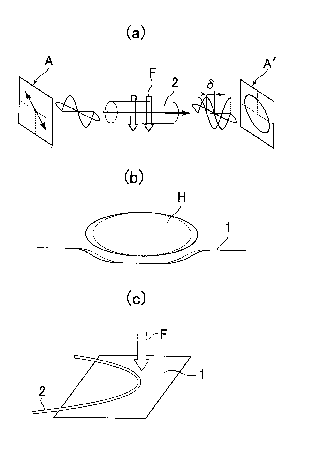
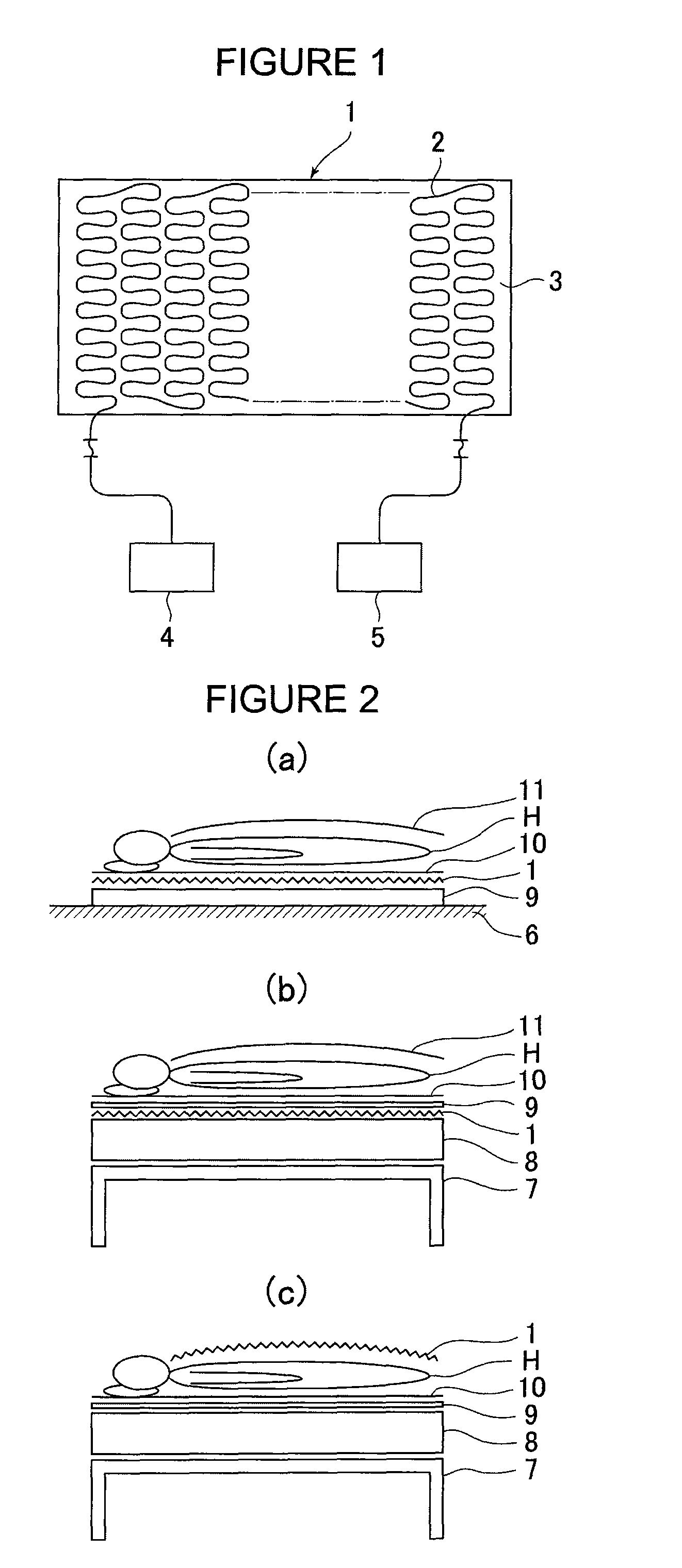
[0119]FIGS. 8(a) to FIG. 8(d) show preferred embodiments of the optical fiber type flat shaped body sensor 1 in accordance with the present invention. As shown in FIG. 3(b) and FIG. 3(c), polarized wave fluctuations caused by vibration and bend stress F applied to the optical fiber 2 become relatively large when vibration and the like are applied in the direction perpendicular to the original bend plane of the optical fiber 2. Therefore, 4 different types of sensors 8(a) to 8(d) have been constructed.

[0120]The optical fiber 2 is affixed to a cloth made sheet 3 (i.e., a flat shaped body consisting of a cloth such as a sheet). The optical fiber is constituted in this case as a single mode optical fiber 2 with a covered outer diameter of approximately 0.5 mm and a conductor clad, which has a diameter of 0.125 mm φ. The optical fiber 2 is fixed with a synthetic resin made adhesive to the flat shaped body 3 made of blended cloth, which is a cloth made of a synthe...

embodiment 2

Illustrative Embodiment 2

[0123]FIG. 9 shows a preferred embodiment in the event that the structure of the optical fiber 2 shown in FIG. 8 is made to be a multi-conductor type (the number of conductors is n) optical fiber, with which improved sensitivity is brought about by polarized wave fluctuations produced due to changes in the shape (form) of the flat shaped body sensor 1. In this embodiment, a light source apparatus 4 and a measuring apparatus 5 for measuring polarized wave fluctuations are connected with the end part of one side of the multi-conductor type optical fiber 2.

embodiment 3

Illustrative Embodiment 3

[0124]FIG. 10 illustrates a method of raising polarized wave fluctuation sensitivity brought about by producing polarized wave fluctuations due to changes in the shapes of the flat shaped body sensor 1. Sensitivity is raised by means of a reflection mirror 18 installed at the end part of one side of the optical fiber 2 in order that light wave signals are transmitted to and fro. In accordance with FIG. 10, 19 designates an optical circulator. An optical coupler can be used as a substitute for the optical circulator 19.


PUM


Abstract

A living body monitoring activity system detects major activities, or feeble living body activities. In a method for monitoring existence of human movements or living body activities in living environments (e.g., sleeping activities involving a bed, a Futon-mat, a pad, or a Tatami-mat), an optical fiber type flat shaped body sensor including an optical fiber affixed or fitted to a flat shaped body is used, and light is emitted into the optical fiber from a light source, and changes of polarized wave conditions of light propagating in the optical fiber are brought about by changes in form of the optical fiber type flat shaped body sensor caused by human movements or living body activities and are detected by a measuring apparatus for polarized wave fluctuations so human activities or movements are discriminated based on the detected value of the polarized wave fluctuations.

Description

[0001]This is a Continuation or Continuation-in-Part of International Patent Application No. PCT / JP2006 / 317297 filed Aug. 25, 2006, which claims priority on Japanese Patent Application No. 2005-250154, filed Aug. 30, 2005. The entire disclosures of the above patent applications are hereby incorporated by reference.TECHNICAL FIELD[0002]The present invention is mainly utilized in fields such as medical care or nursing care and the like, and relates to a method for monitoring living body activities or movements on a floor, a bed or a Tatami-mat, and the like, which makes it possible for human body activities or movements to be sensed or monitored from a distance both automatically and with high accuracy, and the invention includes an optical fiber type flat shaped body sensor used for the same. More specifically, the present invention relates to a method for monitoring living body activities, which makes it possible for all human body activities and movements including respiration, pul...

Claims


Application Information

Patent Timeline
Patent Type & Authority Patents(United States)
IPC IPC(8): A61B5/103A61B5/117
CPCA61B5/103A61B5/113A61B5/6804G01L1/242G01L1/246G01M11/083A61B5/7257A61B2560/0412A61B2562/0233A61B2562/046
Inventor KURONO, MASAHIROMATSUO, SHIROYUTO, AKIRAMEGURI, SHINYAMAENO, TOSHITAKAMATSUDA, HIROSHIGESUZUKI, KENICHITANIGUCHI, KAZUHIKOKATO, KOKICHI
Owner KINDEN CORP
Learn More