Semiconductor integrated circuit
a technology of integrated circuits and semiconductors, applied in the direction of resistors, electrical devices, arrangements responsive to excess voltage, etc., can solve the problems of difficult to reduce the output capacitance cb>total, difficult to make the capacitance cb>2, and difficulty in properly triggering the thyristor, etc., to achieve low output capacitance and reduce the resistance value of the path
- Summary
- Abstract
- Description
- Claims
- Application Information
AI Technical Summary
Benefits of technology
Problems solved by technology
Method used
Image
Examples
first embodiment
[First Embodiment]
[0041]FIG. 6A is a circuit diagram showing a configuration of a semiconductor integrated circuit 10 according to a first embodiment of the present invention. The semiconductor integrated circuit 10 has a VDD pad 11 connected to a power supply line 21, an output pad 12 connected to an output signal line 22, a VSS pad 13 connected to a ground line 23 and a thyristor 14. The VDD pad 11 serves as a power supply terminal to which a power supply voltage is supplied, and the VSS pad 13 serves as a ground terminal to be grounded. The output pad 12 is used to output an output signal to an external unit. The thyristor 14 has a function of discharging ESD surge to the ground line 23 when the ESD surge is applied to the output pad 12.
[0042]A last stage output driver 16 of an internal circuit is connected to the output signal line 22. The last stage output driver 16 has a PMOS transistor P1 connected between the power supply line 21 and the output signal line 22 and an NMOS tra...
second embodiment
[Second Embodiment]
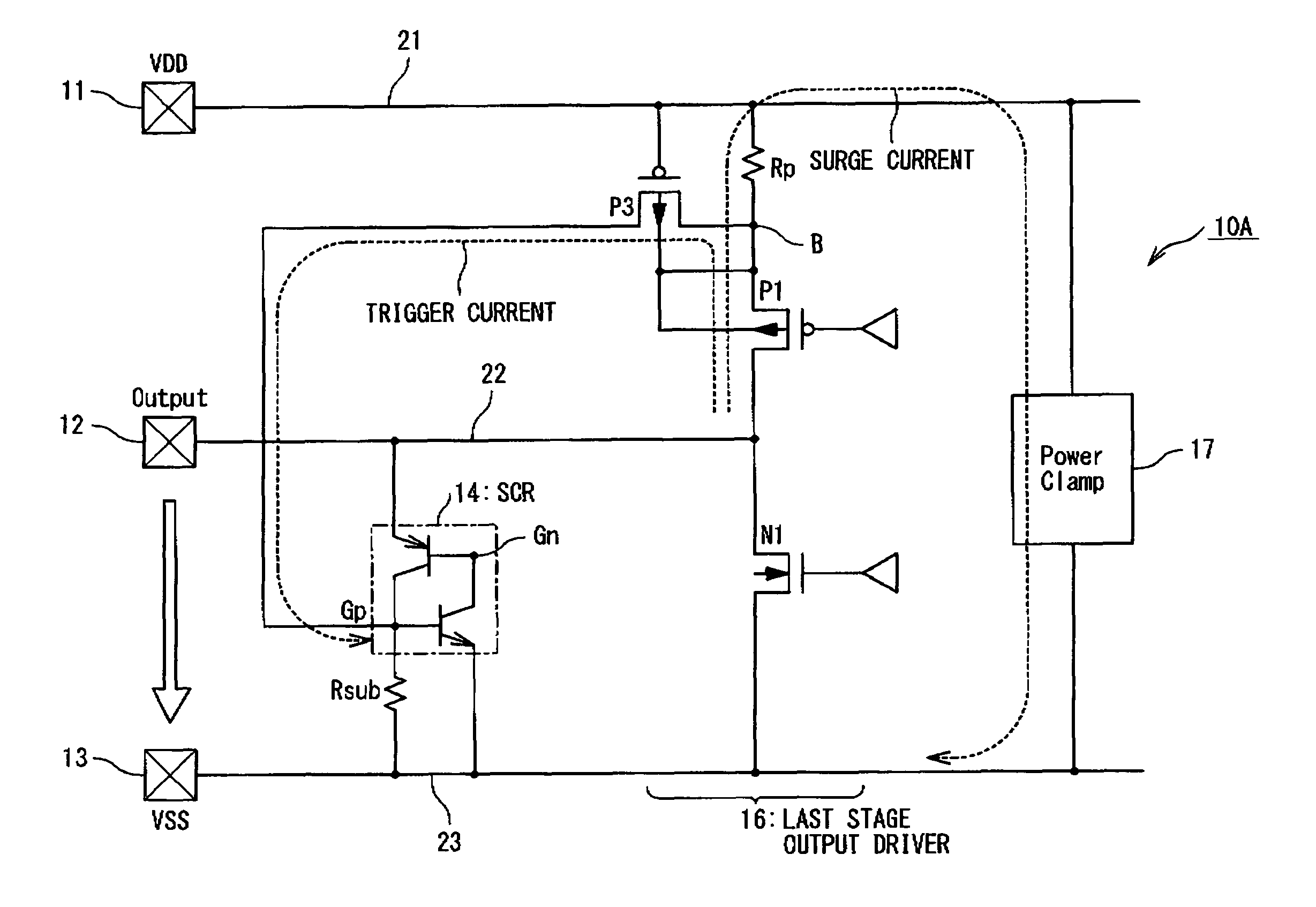
[0052]FIG. 9 is a circuit diagram showing the configuration of a semiconductor integrated circuit 10A according to a second embodiment of the present invention. The semiconductor integrated circuit 10A of the second embodiment has the configuration for protecting the PMOS transistor P1 of the last stage output driver 16 from the electrostatic breakdown. In detail, a resistance element Rp is connected between the power supply line 21 and a node B and the PMOS transistor P1 is connected between the node B and the output signal line 22. The resistance element Rp is used to detect a current flowing through the PMOS transistor P1 as a protection target device. The PMOS transistor P3 used as a trigger device is connected to the P gate Gp of the thyristor 14. The PMOS transistor P3 is connected to the P gate Gp of the thyristor 14 at its drain, is connected to the node B at its source and is connected to the power supply line 21 at its gate. A power clamp 17 is connected...
third embodiment
[Third Embodiment]
[0056]FIG. 10 is a circuit diagram showing the configuration of a semiconductor integrated circuit 10B according to a third embodiment of the present invention. The semiconductor integrated circuit 10B in the third embodiment has the configuration of a combination of the semiconductor integrated circuits 10 and 10A in the first and second embodiments, for protecting both of the NMOS transistor N1 and the PMOS transistor P1 against electrostatic breakdown. In detail, the resistance element Rn is connected between the ground line 23 and the node A and the NMOS transistor N1 is connected between the node A and the output signal line 22. The gate of the NMOS transistor N3 used as the trigger device is connected to the node A. The NMOS transistor N3 is connected to the N gate Gn of the thyristor 14 at its drain, and is connected to the ground line 23 at its source. Furthermore, the resistance element Rp is connected between the power supply line 21 and the node B and th...
PUM
 Abstract
Description
Claims
Application Information
 - R&D
- Intellectual Property
- Life Sciences
- Materials
- Tech Scout
- Unparalleled Data Quality
- Higher Quality Content
- 60% Fewer Hallucinations
Browse by: Latest US Patents, China's latest patents, Technical Efficacy Thesaurus, Application Domain, Technology Topic, Popular Technical Reports.
© 2025 PatSnap. All rights reserved.Legal|Privacy policy|Modern Slavery Act Transparency Statement|Sitemap|About US| Contact US: help@patsnap.com


