
Method and system for forming very low noise imagery using pixel classification

a pixel classification and low noise technology, applied in the field of signal processing, can solve the problems of increasing computation expense relative to a backprojector technique, complex sar imaging, and inability to multiprocessor-based supercomputers to solve complex problems such as fft's two-dimensional, and achieve the effect of reducing false alarm rate and high contrast imag

Inactive Publication Date: 2012-06-05
US SEC THE ARMY THE +1
View PDF7 Cites 31 Cited by
  • Summary
  • Abstract
  • Description
  • Claims
  • Application Information

AI Technical Summary

Benefits of technology

"The patent describes a method for generating high-contrast images with almost no noise using a sparse aperture imaging technique. The method involves classifying each pixel in the image based on its statistics from many realizable sparse aperture images. By doing this, the method can suppress both additive and multiplicative noise. The technique can detect targets with very small amplitudes and can be used in various applications such as ship or building interiors detection, buried mines detection, and medical imaging. The resulting benefits include high-contrast images and a significant reduction in false alarm rate."

Problems solved by technology

Non-uniform spacing requires a Discrete Fourier Transform (DFT) which increases computation expense relative to a backprojector technique.
Also, two-dimensional FFT's are not well suited to multiprocessor-based supercomputers because they face a corner-turn interprocessor communication bottleneck.
SAR imaging is complex for a variety of reasons.
Instead, data may be inputted in a non-uniform manner from an aircraft that is buffeted by the wind or from a ground vehicle that traverses rough ground.
Second, the subject objects need not be point sources but may be dispersive—where energy is stored and “re-radiated” over time.
Ground penetrating SAR adds the complication that the media propagation velocity varies which complicates seismic processing.
For many SAR applications, especially for high-resolution, ultra-wide-angle (UWA), ultra-wide-bandwidth (UWB) surveillance systems, the task is particularly problematic because the data sets are large, real-time operation is essential, and the aperture geometry is not controlled.
Backprojector techniques also allow for non-uniform spacing of the projection data.
However, “energy” from the two point targets is spread throughout the image and creates severe sidelobes.
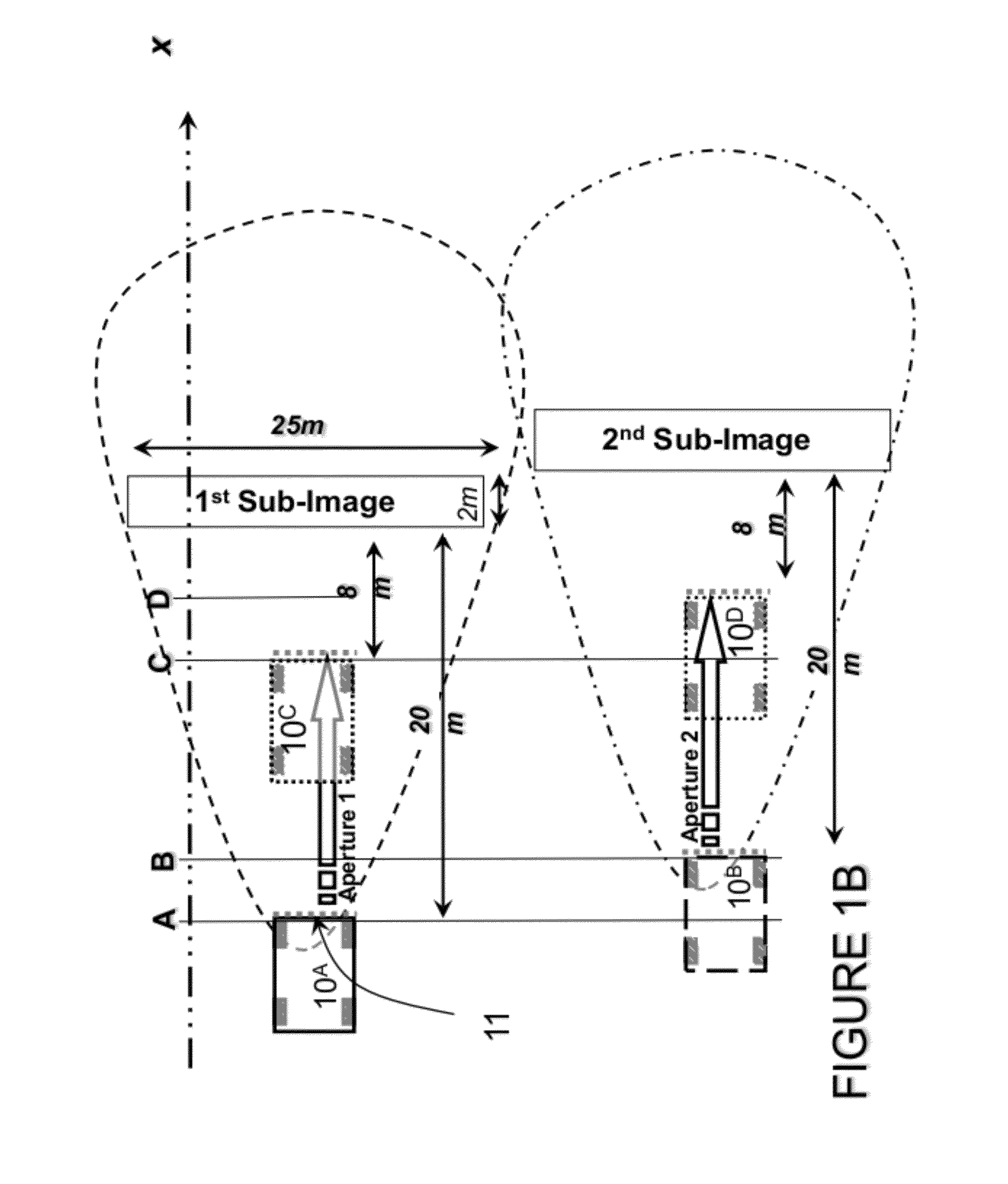
There are two sources that generate the imaging artifacts in this case: a) aperture aliasing (small aperture compared to the large image cross-range swath), and b) the errors from the position measurements system.
In reality, there are many other sources that contribute to the noise floor of the resulting image.
This created a challenging problem for the detection of targets of smaller amplitudes since they might be obscured or even embedded in the noise floor.
There are many sources that cause noise in the resulting image.
Multiplicative noise is much more difficult to deal with since it is data dependent.
Some sources that cause multiplicative noise include: timing jitter in data sampling, small aperture size compared to image area, the under-sampling of aperture samples, the non-uniform spacing between aperture samples, errors in position measurement system, etc.
Multiplicative noise results in undesired sidelobes that create high noise floor in the image and thus limit the ability to detect targets with smaller amplitudes.
Radar and other imaging systems currently suffer various noise sources that prevent the generation of very high contrast images.
As a result, difficult targets (with low amplitudes) are often obscured or even embedded in the noise level of the image background.
Moreover, sidelobes from large targets are mistaken as targets of interest.

Method used


Image

  • Method and system for forming very low noise imagery using pixel classification
  • Method and system for forming very low noise imagery using pixel classification
  • Method and system for forming very low noise imagery using pixel classification

Examples


Embodiment Construction

[0094]The embodiments of the invention and the various features and advantageous details thereof are explained more fully with reference to the non-limiting embodiments that are illustrated in the accompanying drawings and detailed in the following description. It should be noted that the features illustrated in the drawings are not necessarily drawn to scale. Descriptions of well-known components and processing techniques are omitted so as to not unnecessarily obscure the embodiments of the invention. The examples used herein are intended merely to facilitate an understanding of ways in which the embodiments of the invention may be practiced and to further enable those of skilled in the art to practice the embodiments of the invention. Accordingly, the examples should not be construed as limiting the scope of the embodiments of the invention.

[0095]The terminology used herein is for the purpose of describing particular embodiments only and is not intended to limit the full scope of ...


PUM


Abstract

A method and system for generating images from projection data comprising inputting first values representing correlated positional and recorded data; forming an image by processing the projection data utilizing a pixel characterization imaging subsystem to form the SAR imagery utilizing one of a back-projection algorithm or range migration algorithm; integrating positional and recorded data from many aperture positions, comprising: forming the complete aperture A0 comprising collecting the return radar data, the coordinates of the receiver, and the coordinates of the transmitter for each position k along the aperture of N positions; forming an imaging grid comprising M image pixels; selecting and removing a substantial number of aperture positions to form a sparse aperture Aifor L iterations; classifying each pixel in the image into target class based on the statistical distribution of its amplitude across L iterations; otherwise, the pixel is given the value of zero.

Description

CROSS-REFERENCE TO RELATED APPLICATIONS[0001]This application is a continuation-in-part of and claims priority to U.S. patent application Ser. No. 12 / 331,888, filed on Dec. 10, 2008, which is incorporated by reference herein, now U.S. Pat. No. 7,796,829.STATEMENT OF GOVERNMENT INTEREST[0002]The invention described herein may be manufactured, used, and licensed by or for the United States Government.FIELD OF INVENTION[0003]This invention relates broadly to signal processing and in particular to methods and systems for the enhancing and / or processing images.REFERENCE TO PARTIAL COMPUTER PROGRAM LISTING[0004]Appendix A contains a partial computer program listing adapted for a preferred embodiment of the present invention.BACKGROUND OF THE INVENTION[0005]The present invention relates to the generation of images from projection measurements. Examples of images generated from projection measurements include two-dimensional and three-dimensional SAR (synthetic aperture radar) systems. SAR ...

Claims


Application Information

Patent Timeline
Patent Type & Authority Patents(United States)
IPC IPC(8): G01S13/00
CPCG01S7/414G01S13/90G01S13/9017G01S13/9089
Inventor NGUYEN, LAM HUYSICHINA, JEFFREY P.
Owner US SEC THE ARMY THE
Learn More