Magnetic resonance imaging apparatus and chiller
a magnetic resonance imaging and chiller technology, applied in superconducting magnets/coils, instruments, magnetic bodies, etc., can solve the problems of increasing the life of the cooling pipe, increasing the temperature of the gradient magnetic field coil, and increasing the temperature of the cooling pipe. the effect of temperature suppression
- Summary
- Abstract
- Description
- Claims
- Application Information
AI Technical Summary
Benefits of technology
Problems solved by technology
Method used
Image
Examples
first embodiment
[0055
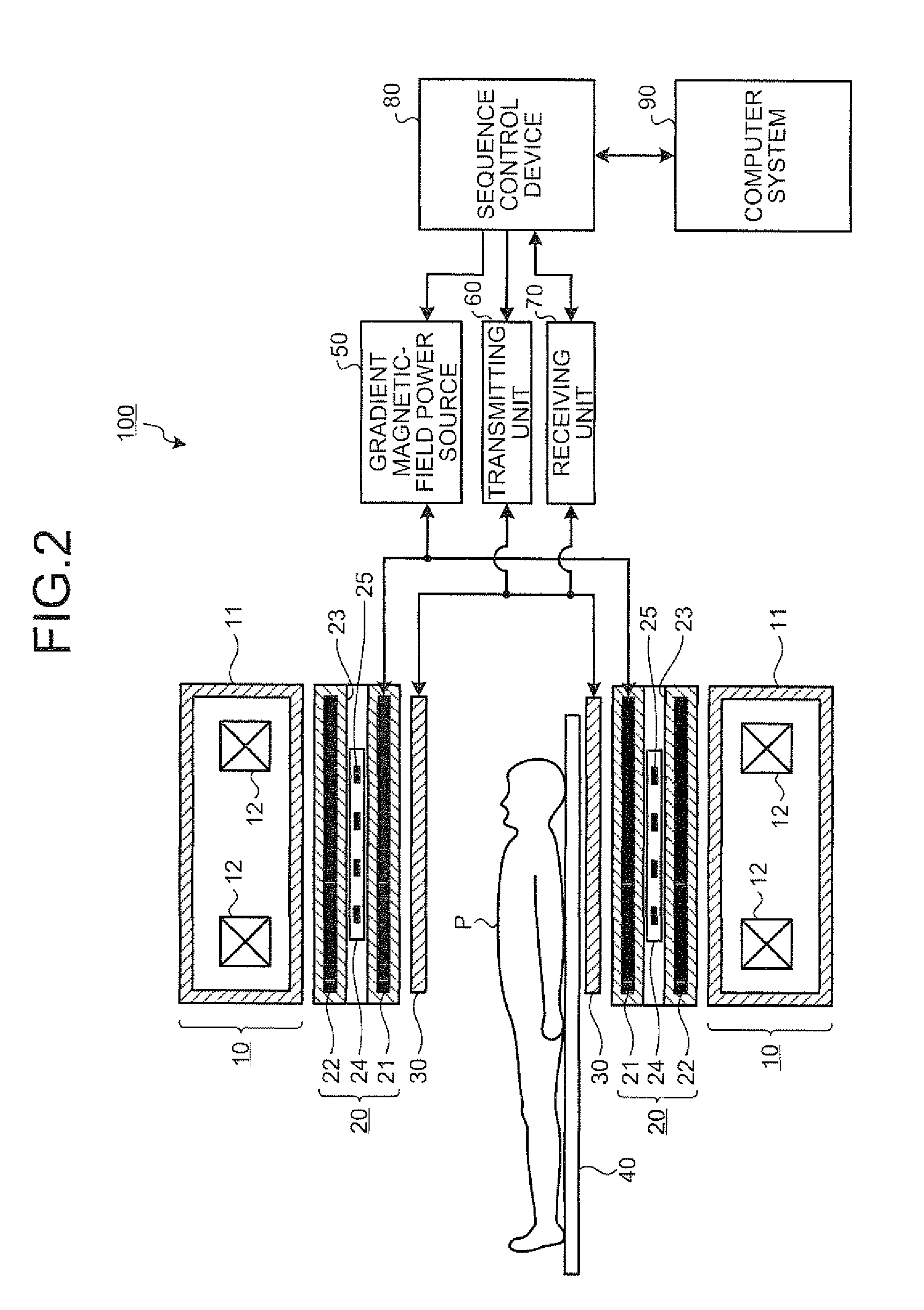
[0056]First of all, cooling of units in an MRI apparatus according to a first embodiment is explained below. FIG. 1 is a schematic diagram for explaining cooling of units of an MRI apparatus according to a first embodiment. An MRI apparatus 100 according to the first embodiment includes various kinds of units required for taking an image of the inside of a subject by using magnetic resonance phenomenon. For example, as shown in FIG. 1, the MRI apparatus 100 includes a gradient magnetic-field coil, a unit A, and a unit B.
[0057]It is assumed that the gradient magnetic-field coil, the unit A, and the unit B generate heat during a scan, therefore, need to be cooled. For this reason, the gradient magnetic-field coil, the unit A, and the unit B are each provided with a cooling pipe for circulating cooling water. Furthermore, the MRI apparatus 100 includes a main chiller 200, and a coil-dedicated chiller 300, as chillers for cooling the gradient magnetic-field coil, the unit A, and th...
second embodiment
[0098
[0099]The first embodiment is explained above in a case where the coil-dedicated chiller 300 is placed in a machine room, and cooling water supplied from the main chiller 200 placed outdoors is flowed into the cooling pipe of the gradient magnetic-field coil 20. However, the present invention is not limited to this.
[0100]For example, if the machine room does not have a space wide enough to place a coil-dedicated chiller, the coil-dedicated chiller can be placed outdoors, and can be configured to flow cooling water from its own device into the cooling pipe of the gradient magnetic-field coil, instead of flowing cooling water supplied from the main chiller into the cooling pipe of the gradient magnetic-field coil.
[0101]A case of such configuration is explained below as a second embodiment. For convenience of explanations, devices and functional units that work similarly to the devices and the functional units explained in the first embodiment are assigned with the same reference ...
third embodiment
[0108
[0109]The first and second embodiments are explained above in a case where the temperature of cooling water to be flowed into the cooling pipe of the gradient magnetic-field coil is change in accordance with the amount of change in temperature of cooling water flowing out from the cooling pipe of the gradient magnetic-field coil. However, the present invention is not limited to this.
[0110]For example, the coil-dedicated chiller can be configured to change the temperature of cooling water to be flowed into the cooling pipe of the gradient magnetic-field coil by mixing cooling water supplied from the main chiller with cooling water that is at a constant temperature (for example, 10° C.) lower than the cooling water supplied from the main chiller.
[0111]A case of such configuration is explained below as a third embodiment. For convenience of explanations, devices and functional units that work similarly to the devices and the functional units explained in the first and second embod...
PUM
 Abstract
Description
Claims
Application Information
 - R&D
- Intellectual Property
- Life Sciences
- Materials
- Tech Scout
- Unparalleled Data Quality
- Higher Quality Content
- 60% Fewer Hallucinations
Browse by: Latest US Patents, China's latest patents, Technical Efficacy Thesaurus, Application Domain, Technology Topic, Popular Technical Reports.
© 2025 PatSnap. All rights reserved.Legal|Privacy policy|Modern Slavery Act Transparency Statement|Sitemap|About US| Contact US: help@patsnap.com


