
Motorcycle

a technology for motorcycles and motors, applied in the field of motorcycles, can solve the problems of difficult concentration of mass and lowering of difficult to concentrate mass, and difficult to lower so as to achieve the effect of enhancing the output of the engine, reducing the center of gravity, and sufficient length

Active Publication Date: 2012-05-22
HONDA MOTOR CO LTD
View PDF42 Cites 19 Cited by
  • Summary
  • Abstract
  • Description
  • Claims
  • Application Information

AI Technical Summary

Benefits of technology

The present invention provides a motorcycle with an engine arranged between front and rear wheels, and an intake part and exhaust part connected to the front and rear of a cylinder. The intake part is designed to concentrate mass and lower the center of gravity, and the exhaust part is designed to prevent heat from hitting the engine. The intake part is connected to the cylinder in a V-type space, and a duct and stay support the radiator. The exhaust pipe extends from the exhaust port towards the back of the cylinder and is divided into an exhaust upstream side and a exhaust downstream side. The oil pan is positioned below the engine and the exhaust duct extends sideways in the vehicle body. These design features optimize the arrangement of the intake and exhaust parts, and improve the compactness of the motorcycle and the performance of the engine.

Problems solved by technology

When the structure of an air cleaner is arranged on the upside of a cylinder as in examples of the related art is adopted, an intake part is arranged on the upside of the cylinder, and the concentration of mass and the lowering of the center of gravity are made difficult.
However, as exhaust parts are longitudinally distribution in a V-type engine vehicle as in an example of the related art, it is difficult to concentrate mass.
In addition, as a muffler is located in a high position, it is difficult to lower the center of gravity.
Further, in a vehicle provided with a forward inclined engine, as an exhaust pipe is arranged in a substantial L type in a side view simply from the upside to the downside in front of a cylinder, mass easily shifts forward, as an intake part is located on the upside on the back side of the cylinder, the mass is similarly dispersed, and it is also difficult to lower the center of gravity.

Method used


Image

  • Motorcycle
  • Motorcycle
  • Motorcycle

Examples


Embodiment Construction

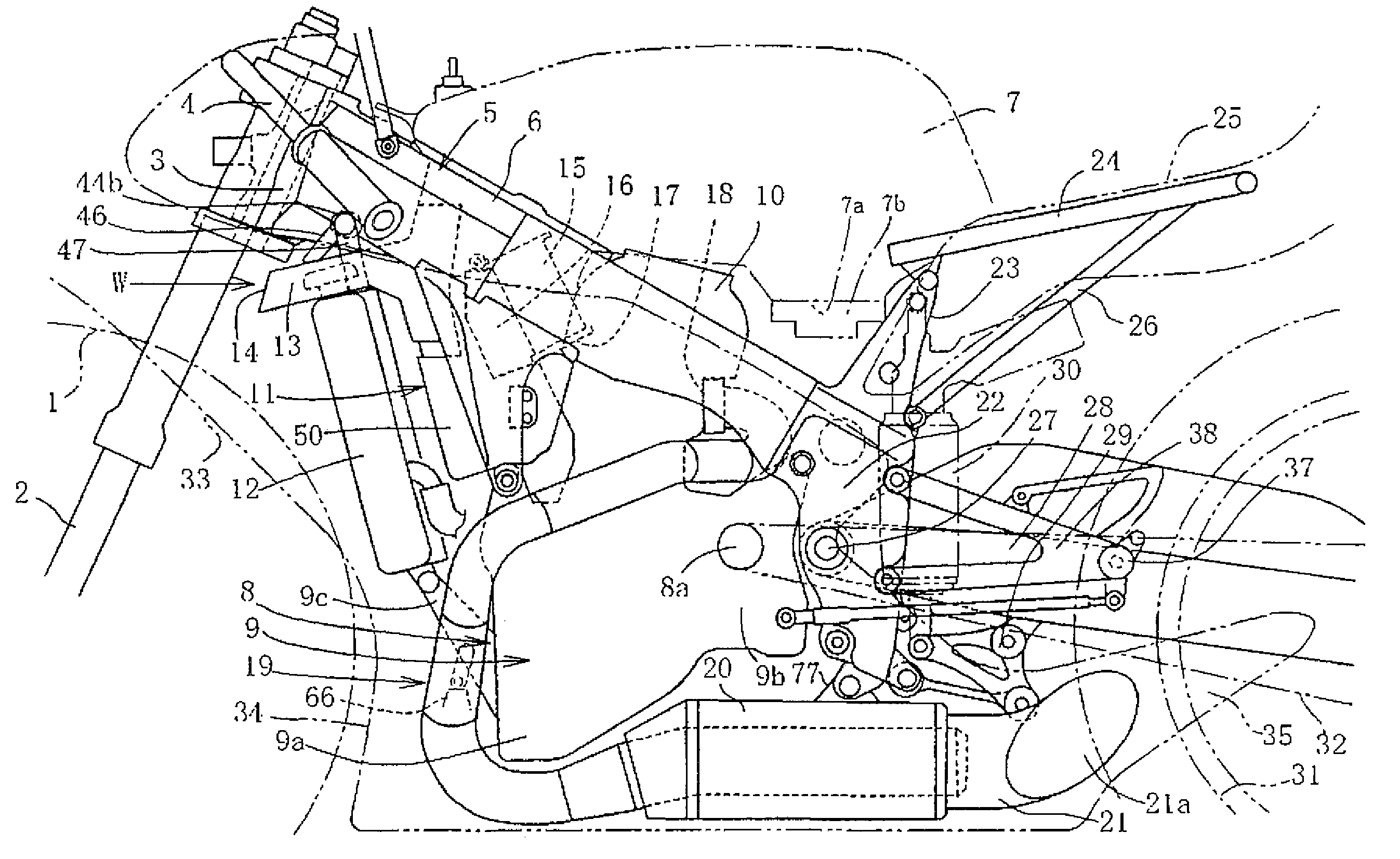
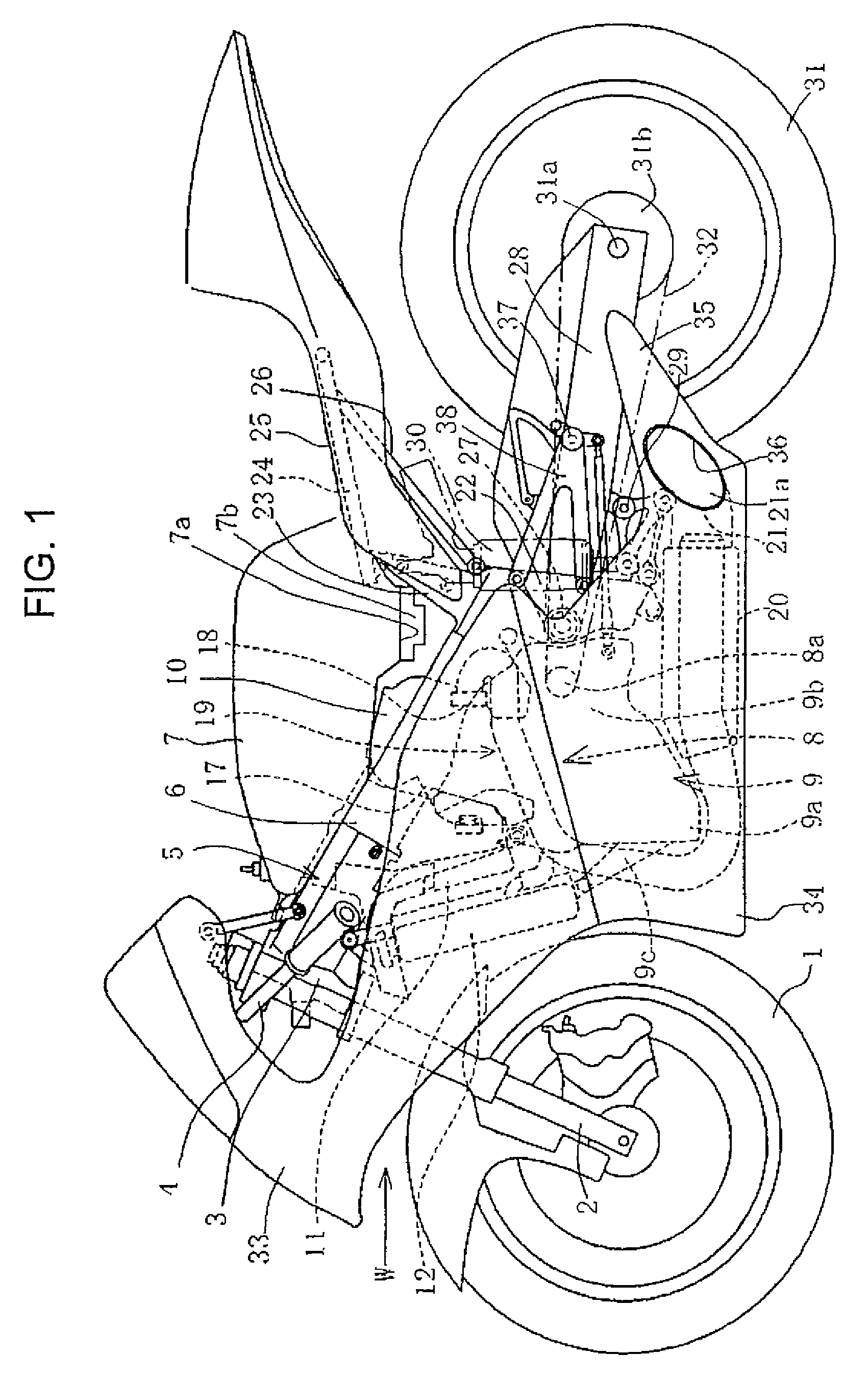
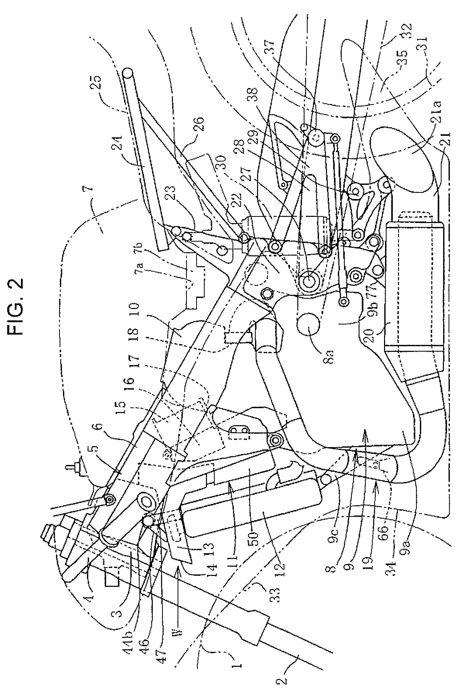
[0054]Referring to the drawings, one embodiment will be described below. FIG. 1 is a side view showing the appearance in a state in which a body cover is installed of this motorcycle and FIG. 2 is a side view showing a main part of a vehicle body in which a part of appearance parts such as the body cover are shown by an imaginary line. In FIGS. 1 and 2, a front wheel 1 is provided wherein the front wheel is turnably supported by a head pipe 3 via a front fork 2, and is steered by a handlebar 4.

[0055]The head pipe 3 is provided to a front end of a body frame 5, a fuel tank 7 is supported on / by a main frame 6 extended diagonally downward and backward of the body frame, and an engine 8 is supported on the downside of the fuel tank. A downward protruded part 7b is formed from the rear of a bottom 7a of the fuel tank 7 and a built-in fuel pump (not shown) is attached to the downward protruded part. Space for housing the downward protruded part 7b is formed at the back of a cylinder 10 an...


PUM


Abstract

To concentrate mass, to lower the center of gravity, to efficiently and optimally arrange an intake part for making a compact vehicle body. A cylinder inclined to the rear is arranged under a fuel tank and a body of an intake box is housed between a radiator arranged in front of the cylinder and the cylinder. An upper part of the body of the intake box is fixed to a body frame at the bottom of the fuel tank and air taken in is supplied to an intake port through an intake funnel and a throttle body respectively built-in. A lid of an intake duct can be extractably inserted into a window hole provided to the front of the body, a duct part integrated with the lid is arranged over the radiator, and an air intake guide port takes a flow of air in front of the radiator.

Description

CROSS-REFERENCE TO RELATED APPLICATIONS[0001]The present application claims priority under 35 USC 119 to Japanese Patent Application No. 2007-341577 and Japanese Patent Application No. 2007-341578 both filed on Nov. 30, 2007 the entire contents of which are hereby incorporated by reference.BACKGROUND OF THE INVENTION[0002]1. Field of the Invention[0003]The present invention relates to a motorcycle, particularly relates to a motorcycle provided with an intake part that can concentrate mass, can lower the center of gravity and can make the motorcycle compact.[0004]According to an embodiment of the invention, a vertical direction, a longitudinal direction and a lateral direction are based upon a condition that the front of a vehicle body is located ahead in a traveling direction. In addition, the inside denotes the center side of the vehicle body and the outside denotes its reverse side. Further, the backward inclination of a cylinder denotes a condition in which the upside of the cyli...

Claims


Application Information

Patent Timeline
Patent Type & Authority Patents(United States)
IPC IPC(8): B60K13/02
CPCB62K11/04B62M7/02
Inventor HIRAMATSU, KINUOKURAYOSHI, YOSHIYUKI
Owner HONDA MOTOR CO LTD
Learn More