Method and system for adjusting the frequency of a resonator assembly for a plasma lamp

a resonator assembly and plasma lamp technology, applied in the field of lighting techniques, can solve the problems of electrode-less lamps still having many limitations, consuming too much energy of edison bulbs, and generally inefficient, so as to reduce the tolerance of the dimensions of resonators, improve manufacturing yield, and simplify manufacturing

Active Publication Date: 2012-05-15
TOPANGA USA
View PDF27 Cites 2 Cited by
  • Summary
  • Abstract
  • Description
  • Claims
  • Application Information

AI Technical Summary

Benefits of technology

[0010]According to the present invention, techniques for lighting are provided. In particular, the present invention provides a method and device using a plasma lighting device having one of a plurality of base configurations. More particularly, the present invention provides a method and resulting system for adjusting a frequency for a resonator assembly for a plasma lamp, which can be used for a variety of applications. The ability to adjust (tune) the frequency of the resonator assembly significantly improves manufacturing yield, simplifies manufacturing by reducing the tolerances of the dimensions of the resonator, and improves lamp performance. In addition one can compensate for any changes in the resonant frequency of the resonator caused by temperature fluctuations or aging. The plasma lamps have applications such as stadiums, security, parking lots, military and defense, streets, large and small buildings, vehicle headlamps, aircraft landing, bridges, warehouses, uv water treatment, agriculture, architectural lighting, stage lighting, medical illumination, microscopes, projectors and displays, any combination of these, and the like.
[0017]Benefits are achieved over pre-existing techniques using the present invention. In a specific embodiment, the present invention provides a method and device having configurations of input, output, and feedback coupling elements that provide for electromagnetic coupling to the bulb whose power transfer and frequency resonance characteristics that are largely independent of the conventional dielectric resonator, but can also be dependent upon conventional designs. In a preferred embodiment, the present invention provides a method and configurations with an arrangement that provides for improved manufacturability as well as design flexibility. Other embodiments may include integrated assemblies of the output coupling element and bulb that function in a complementary manner with the present coupling element configurations and related methods for street lighting applications. Still further, the present method and device provide for improved heat transfer characteristics, as well as further simplifying manufacturing and / or retrofitting of existing and new street lighting, such as lamps, and the like. In a specific embodiment, the present method and resulting structure are relatively simple and cost effective to manufacture for commercial applications. In a preferred embodiment, the present lamp includes a tuning device that allows for more efficient manufacturing, lamp setup, and maintenance. Depending upon the embodiment, one or more of these benefits may be achieved. These and other benefits may be described throughout the present specification and more particularly below.

Problems solved by technology

Although highly successful, the Edison bulb consumes too much energy and is generally inefficient.
Fluorescent lighting is much more efficient than incandescent lighting, but often has a higher initial cost.
Although somewhat successful, the electrode-less lamp still had many limitations.
As an example, electrode-less lamps have not been successfully deployed on a wide scale.

Method used


Image

  • Method and system for adjusting the frequency of a resonator assembly for a plasma lamp
  • Method and system for adjusting the frequency of a resonator assembly for a plasma lamp
  • Method and system for adjusting the frequency of a resonator assembly for a plasma lamp

Examples


Embodiment Construction

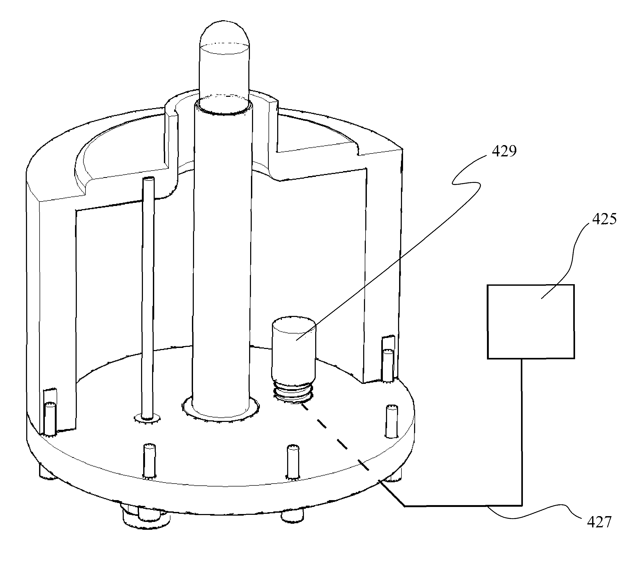
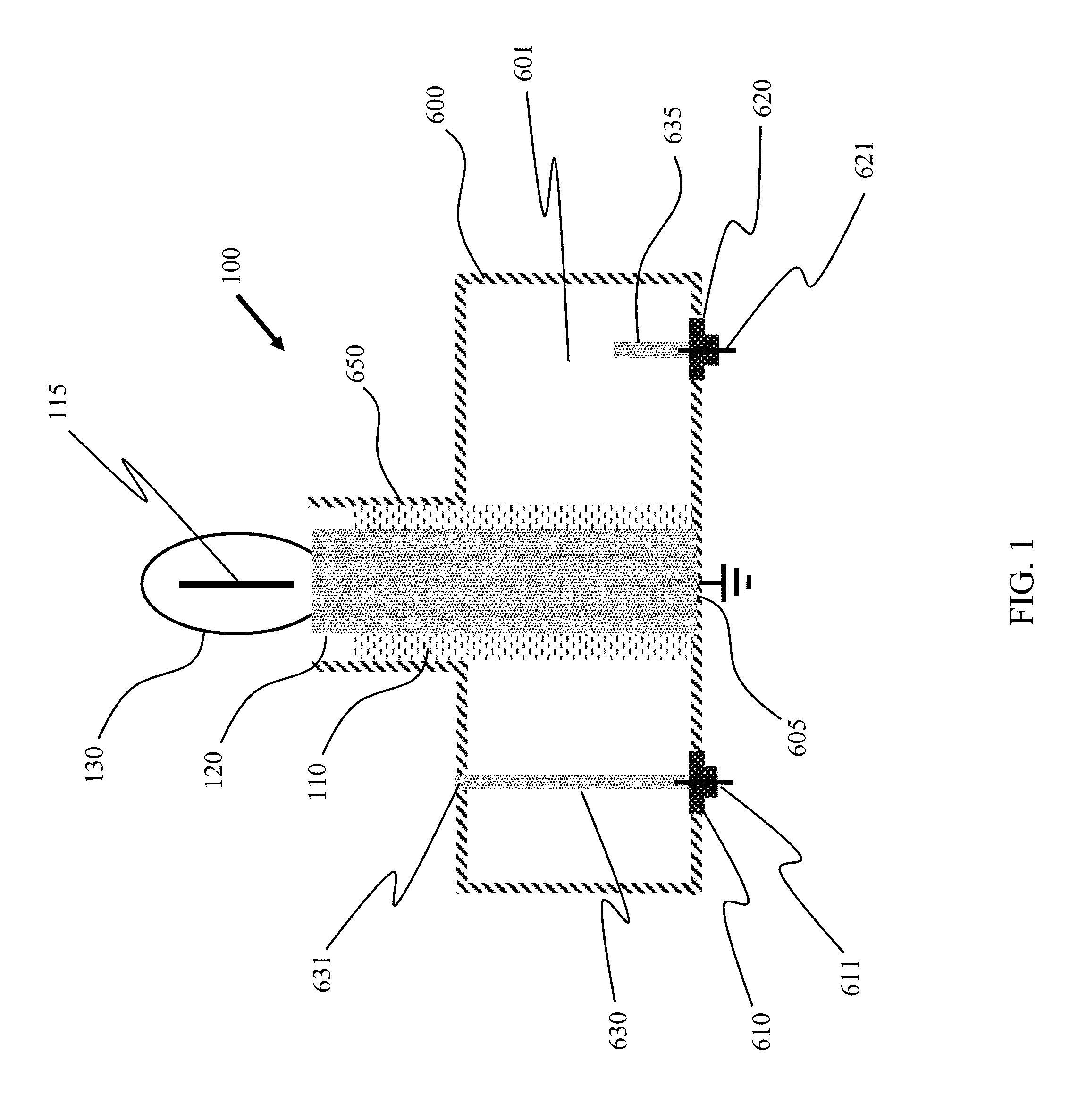
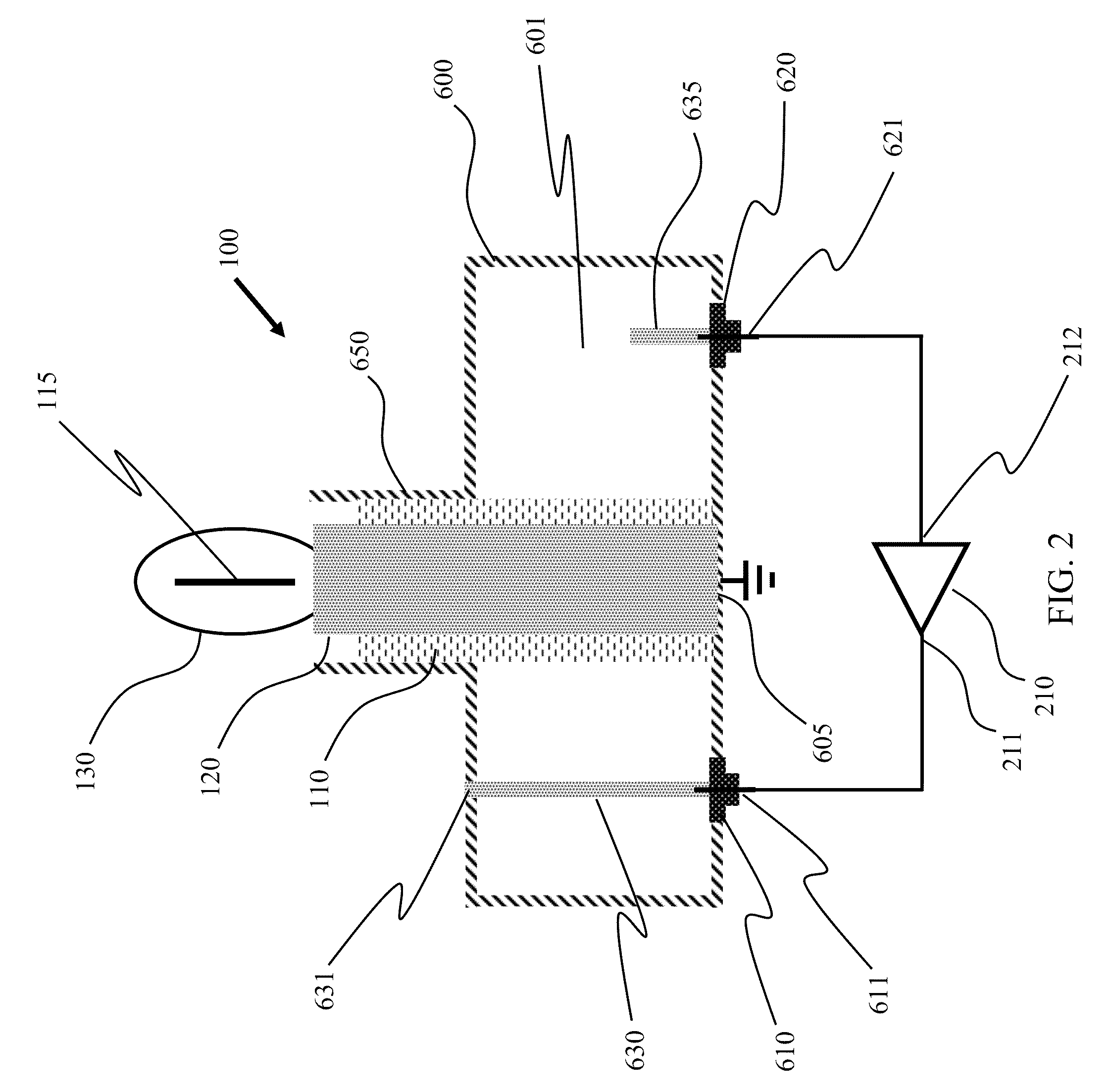
[0029]According to the present invention, techniques for lighting are provided. In particular, the present invention provides a method and device using a plasma lighting device having one of a plurality of base configurations, e.g., compact air resonator, air resonator, air resonator including a dielectric insert or sleeve. More particularly, the present invention provides a method and resulting system for adjusting a frequency for a resonator assembly for a plasma lamp, which can be used for a variety of applications. Merely by way of example, such plasma lamps can be applied to applications such as stadiums, security, parking lots, military and defense, streets, large and small buildings, vehicle headlamps, aircraft landing, bridges, warehouses, uv water treatment, agriculture, architectural lighting, stage lighting, medical illumination, microscopes, projectors and displays, any combination of these, and the like.

[0030]The following description is presented to enable one of ordin...


PUM


Abstract

A plasma electrodeless lamp comprises a substantially hollow metallic body, closely receiving two coupling elements, the first coupling element connected to the output of an RF amplifier, and the second coupling element connected to the input of an RF amplifier. The first coupling element is conductively connected (grounded) to metallic lamp body at its top surface, while the second coupling element is not. The lamp further comprises a vertical metallic post, the post being grounded to the metallic lamp body at the post's bottom surface. The lamp further comprises a dielectric sleeve which closely receives the metallic post, and which is in turn closely supported by the lamp body or alternatively or in combination a tuning stub. The lamp further comprises a bulb that is closely received by the metallic post, and that encloses a gas-fill which forms a radiant plasma when excited.

Description

CROSS-REFERENCES TO RELATED APPLICATIONS[0001]This application claims priority to U.S. Provisional Patent Application No. 61 / 117,485, filed Nov. 24, 2008, commonly assigned, and hereby incorporated by reference herein.STATEMENT AS TO RIGHTS TO INVENTIONS MADE UNDER FEDERALLY SPONSORED RESEARCH OR DEVELOPMENT[0002]Not ApplicableREFERENCE TO A “SEQUENCE LISTING,” A TABLE, OR A COMPUTER PROGRAM LISTING APPENDIX SUBMITTED ON A COMPACT DISK[0003]Not ApplicableBACKGROUND OF THE INVENTION[0004]The present invention relates generally to lighting techniques. In particular, the present invention provides a method and device using a plasma lighting device having one of a plurality of base configurations. More particularly, the present invention provides a method and resulting system for adjusting a frequency for a resonator assembly of a plasma lighting device. Merely by way of example, such configurations can include at least warehouse lamps, stadium lamps, lamps in small and large buildings,...

Claims


Application Information

Patent Timeline
Patent Type & Authority Patents(United States)
IPC IPC(8): H01J19/80
CPCH01J65/044
Inventor ESPIAU, FREDERICK M.MATLOUBIAN, MEHRANBROCKETT, TIMOTHY J.
Owner TOPANGA USA
Why Eureka
Try Eureka