
Optical recording method and optical recording apparatus

a recording method and optical recording technology, applied in the field of optical recording methods and optical recording apparatuses, can solve the problems of light source cost problems, and achieve the effect of reducing the size and cost of the optical system, and effective causing light absorption

Inactive Publication Date: 2012-04-24
SONY CORP
View PDF8 Cites 2 Cited by
  • Summary
  • Abstract
  • Description
  • Claims
  • Application Information

AI Technical Summary

Benefits of technology

This approach enables the formation of recording marks with significantly lower light power, reducing costs and improving energy efficiency while maintaining effective mark formation, as the continuous-wave laser extends the excitation state, allowing for precise control over the recording process.

Problems solved by technology

For example, in a case where an ablation is caused with respect to a material using a CW (Continuous Wave) laser, high average light energy of several watts is required for causing a thermal decomposition that is a principle of the ablation, which causes a cost problem of a light source.

Method used


Image

  • Optical recording method and optical recording apparatus
  • Optical recording method and optical recording apparatus
  • Optical recording method and optical recording apparatus

Examples


Embodiment Construction

[0057]Hereinafter, embodiments of the present invention will be described with reference to the drawings.

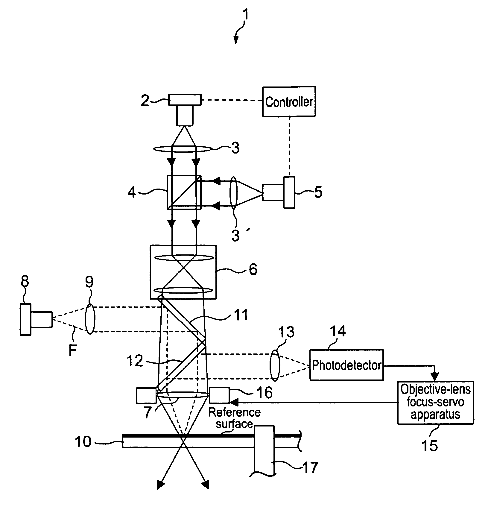
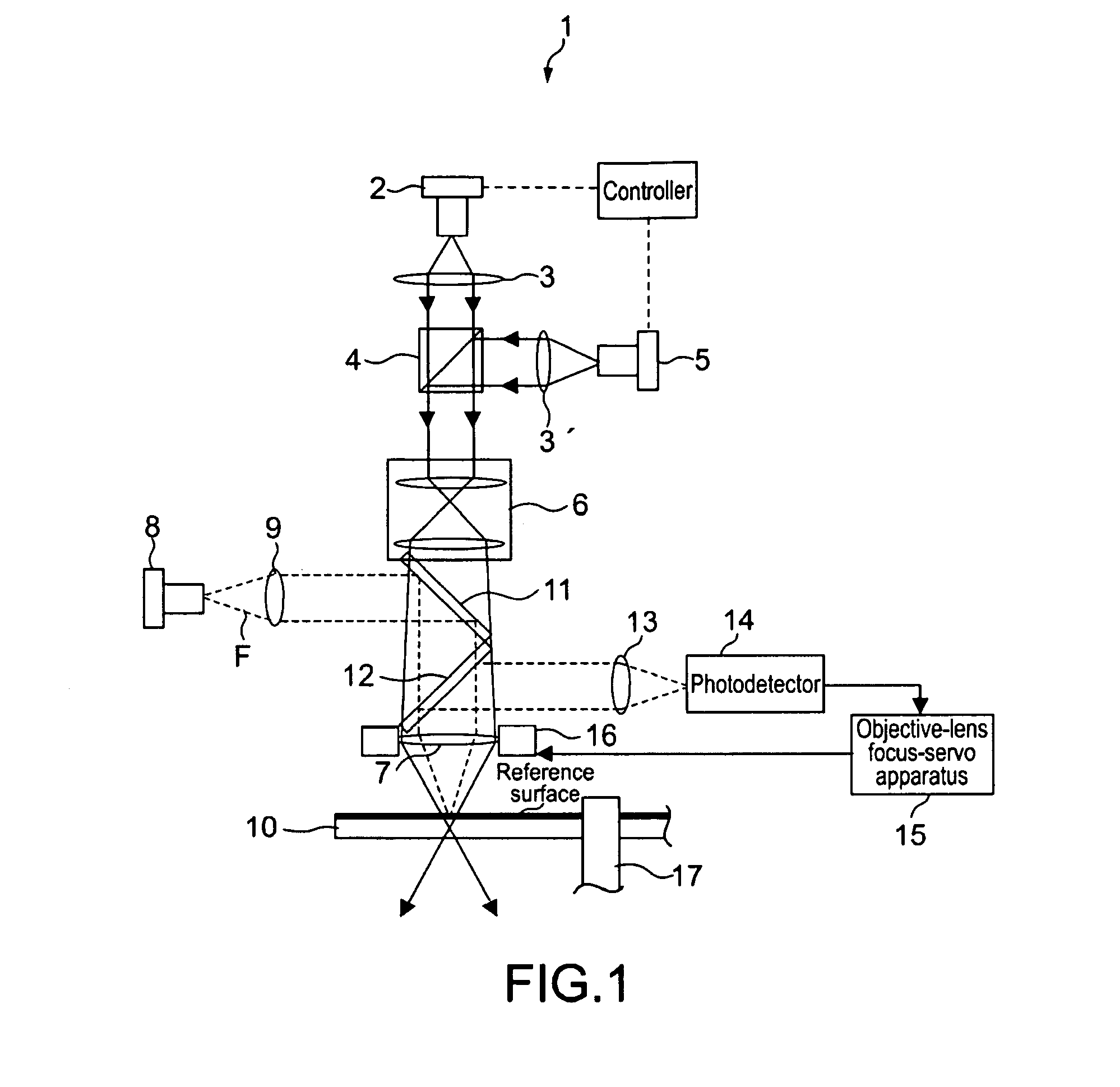
[0058]FIG. 1 is a block diagram showing an optical recording apparatus according to an embodiment of the present invention.

[0059]As shown in FIG. 1, an optical recording apparatus 1 includes a mode-locked laser 2, lenses 3 and 3′, a polarization beam splitter 4, a CW (Continuous Wave) laser 5, a relay lens 6, an objective lens 7, a servo-only laser 8, a lens 9, a beam splitter 11, a beam splitter 12, a focusing lens 13, a photodetector for focus servo 14, an objective-lens focus-servo apparatus 15, an objective-lens actuator 16, and a spindle 17.

[0060]The mode-locked laser 2 generates ultrashort-pulse laser light at predetermined time intervals. The ultrashort pulse means that the pulse has a pulse width of a femtosecond to 100 picoseconds order, for example. The ultrashort-pulse laser light has a frequency of 500 MHz and a wavelength of 405 nm and is used for recording. As a las...


PUM

PropertyMeasurementUnit
pulse poweraaaaaaaaaa
wavelengthaaaaaaaaaa

Abstract

Disclosed is an optical recording method. The optical recording method includes irradiating an area where a recording mark is formed in a medium with a pulse train of laser light, and irradiating the area where the recording mark is formed with continuous-wave laser light that is continuously output.

Description

CROSS REFERENCES TO RELATED APPLICATIONS[0001]The present invention contains subject matter related to Japanese Patent Application JP 2008-081323 filed in the Japanese Patent Office on Mar. 26, 2008, the entire contents of which being incorporated herein by reference.BACKGROUND OF THE INVENTION[0002]1. Field of the Invention[0003]The present invention relates to an optical recording method and an optical recording apparatus for recording information by irradiating a medium with light.[0004]2. Description of the Related Art[0005]There have been proposed various bit-by-bit volumetric recordings with respect to a recording medium. For example, a 3D pit recording with respect to a transparent medium has been proposed (see, “Three-Dimensional Optical Data Storage in Vitreous Silica”, written by Hirao et al., Jpn. J. Appl. Phys. Vol. 37 (1998) pp. L1527-L1530 (hereinafter, referred to as Non-patent Document 1)). Further, mark formation on an organic medium with foam due to a nonlinear opt...

Claims


Application Information

Patent Timeline
Patent Type & Authority Patents(United States)
IPC IPC(8): G11B7/00
CPCG11B7/00451G11B7/127G11B2007/0009G11B7/0045G11B7/126
Inventor UEDA, DAISUKEIWAMURA, TAKASHI
Owner SONY CORP
Learn More