
Method for protection of energy storage source, and in particular motor vehicle battery

a technology for energy storage sources and motor vehicles, applied in the direction of electric vehicles, electrical apparatus, control systems, etc., can solve the problems of affecting the safety of the environment,

Active Publication Date: 2012-04-24
VALEO EQUIP ELECTRIC MOTEUR
View PDF7 Cites 4 Cited by
  • Summary
  • Abstract
  • Description
  • Claims
  • Application Information

AI Technical Summary

Benefits of technology

The invention is a method and regulator for protecting an energy storage source, such as a battery in a motor vehicle, from overloading caused by prolonged use of the battery. The method involves measuring the charge level of the battery and comparing it to a reference value. If the charge level exceeds the reference value, the excitation applied to the rotary electric machine is interrupted. The regulator receives information about the charge level and the functioning mode of the rotary electric machine and uses it to determine the appropriate excitation level for the machine. The regulator can also receive information about the speed of rotation of the rotor and use it to control the functioning mode of the rotary electric machine. The technical effect of the invention is to provide a reliable and effective way to protect energy storage sources in vehicles and other systems from overloading.

Problems solved by technology

In the event of accidental disconnection of the phase screw on the vehicle, the regulator may be deprived of the possibility of obtaining information on the speed of rotation of the alternator, and this regulator, when it is functioning in pre-excitation mode PRE_EXC, may remain blocked functioning in this pre-excitation mode.
This situation can become dangerous because of possible overloading of the battery, giving rise to excess voltage on the network on board the vehicle, in the case when the alternator functions for a prolonged period of time in the pre-excitation mode (in particular despite an alert given for example by a lamp, with the driver of the vehicle ignoring this alert).

Method used


Image

  • Method for protection of energy storage source, and in particular motor vehicle battery
  • Method for protection of energy storage source, and in particular motor vehicle battery

Examples


Embodiment Construction

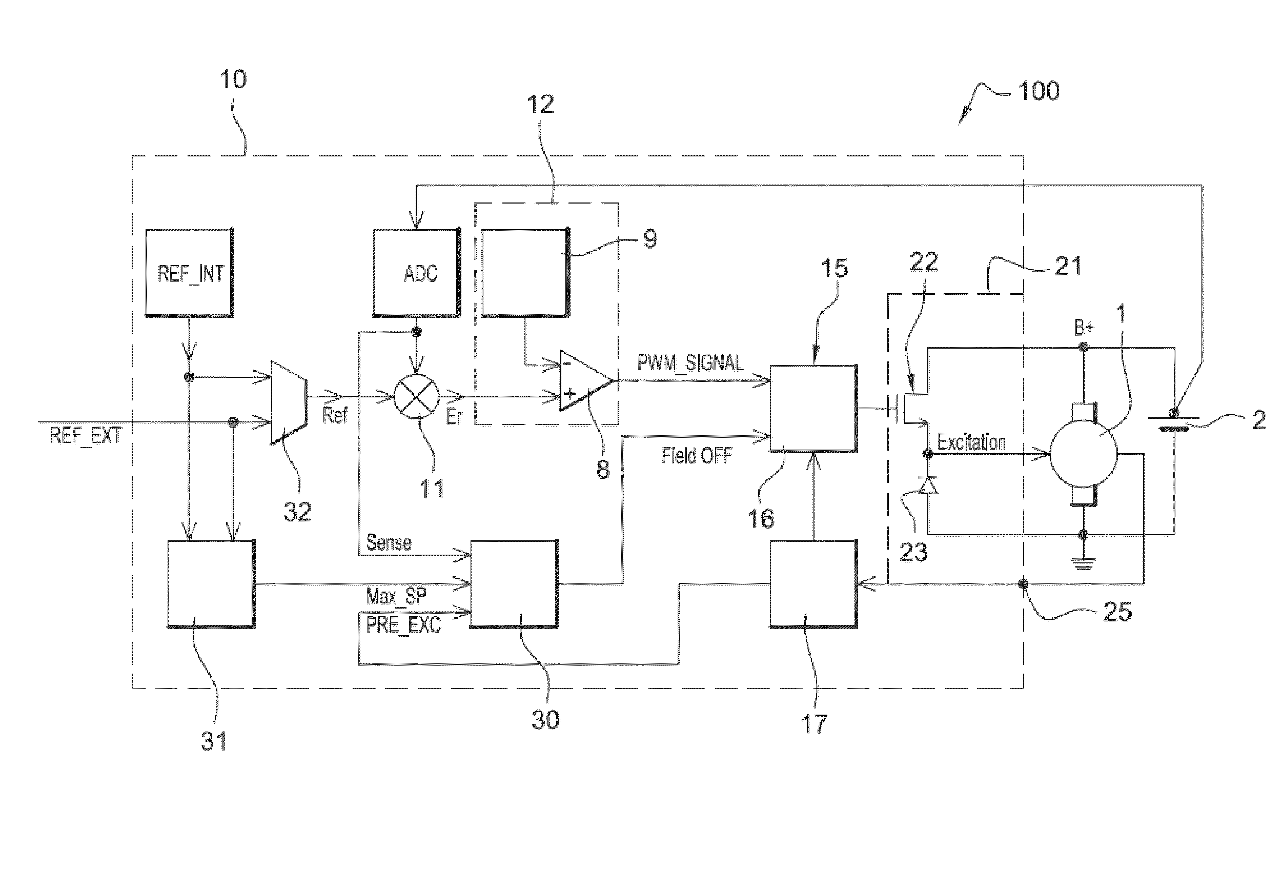
[0041]This alternator 1 can be rotated by an internal combustion engine of the motor vehicle, in order to produce electric energy.

[0042]In a known manner, the alternator 1 comprises firstly a stator, comprising windings which in the example described form three phases, and secondly a rotor comprising an excitation winding.

[0043]As a variant, the machine 1 can be an alternator-starter.

[0044]The alternator 1 is connected to a battery 2 which is on board the vehicle.

[0045]The assembly 100 additionally comprises a regulator 10 for the alternator 1, which regulator 10 can supply an electric current, the intensity of which varies according to excitation pulses or signals.

[0046]The regulator 10 comprises a differential amplifier 11, which is designed to supply error information Er which is representative of the difference between a command Ref and a voltage value, converted by the block ADC from analogue to digital, at a terminal B+ of the alternator 1 which is connected to the battery 2.

[...


PUM


Abstract

A method for protection of an energy storage source (2), in particular a battery of a motor vehicle, against possible overloading caused by prolonged application of an electric voltage to the energy storage source, this voltage being generated at least partially by a rotary electric machine (1) such as an alternator or an alternator-starter, the method comprising the following steps:permitting measurement of a charge level of the energy storage source, this charge level being represented for example by a voltage measured at the terminals of the energy storage source or a PWM signal, while the rotary electric machine is functioning in a predetermined functioning mode, and electric excitation is being applied to it;comparing a value (SENSE) of this measurement with a reference value (Max_SP);if the value measured for the energy storage source is greater than the reference value, interrupting the excitation applied to the rotary electric machine.

Description

[0001]This application foreign priority rights and claims benefit under 35 U.S.C. 119 based on French patent application no 08 / 55734, which is hereby incorporated by reference in its entirety.BACKGROUND OF THE INVENTION[0002]1. Field of the Invention[0003]The invention relates in particular to a method for protection of an energy storage source, in particular a motor vehicle battery.[0004]2. Description of Related Art[0005]Patent EP 920 722 B1 describes a system for regulation of a generator on a motor vehicle.[0006]It is known to impose on a rotary electric machine such as an alternator a functioning mode which is selected from amongst a plurality of predetermined modes.[0007]These modes are imposed by a states machine, and correspond for example to the following modes:[0008]Stoppage mode, known as the STAND_BY mode, in which the excitation of the rotor is maintained at 0% in cyclical ratio terms;[0009]Timing mode, known as the TIMER mode, in which the excitation is cut off for a p...

Claims


Application Information

Patent Timeline
Patent Type & Authority Patents(United States)
IPC IPC(8): H02H7/06
CPCH02J7/163Y02T10/7005Y02T10/70
Inventor TISSERAND, PIERRECHASSARD, PIERREGENDRON, VINCENT
Owner VALEO EQUIP ELECTRIC MOTEUR
Learn More