Wildlife deterrent for high voltage supporting members

a technology of supporting members and deterrents, which is applied in the direction of machine supports, movable shelf cabinets, and dismountable cabinets, etc., can solve the problems of sudden or permanent outage, animal death, and disruption of power supply to customers

Active Publication Date: 2012-04-17
ECO ELECTRICAL SYST
View PDF45 Cites 4 Cited by
  • Summary
  • Abstract
  • Description
  • Claims
  • Application Information

AI Technical Summary

Benefits of technology

[0013]In one embodiment, a wildlife deterrent for a utility support structure is attached to a conductor / insulator supporting member between two conductors. The deterrent includes a bracket for attachment to a supporting member, a separate center support piece having an adjustable height arm connector, and two variable-length arms pivotally attached to the arm connector on the center support piece, where the other ends of the arms are connectable to the supporting member. The variable-length arms may be adjustable-length arms or an assortment of arms of different lengths. The deterrent forms a triangle shape when connected together, and since the height of the arm connector on the center support and the lengths of the arms are variable, the optimal angle of the arms can be achieved and maintained no matter what the separation between the conductors, and the gap between the arms and the conductors can be optimal for both deterrence and flashover prevention.
[0021]The invention allows many different sizes and shapes of deterrents to be created using the same parts. Forming a deterrent to have customized characteristics, depending on the conductor spacing and type of support structure, enables a lineman to optimize the deterrent in the field without requiring the stocking of many different sizes and shapes of deterrents.

Problems solved by technology

If a bird, squirrel, or other animal perched or sitting on a support structure, supporting member, conductor, or insulator completes a circuit phase to phase, or phase to ground, a flashover will occur, resulting in an outage, disrupting power to customers, and the death of the animal.
If an animal approaches the energized conductor or insulator and provides a conductive path to ground, or if an animal effectively reduces the necessary separation or clearance of two energized conductors, a short will occur in the circuit, resulting in a momentary or permanent outage.
Additionally, the shorting could also be caused by an improperly installed or damaged wildlife deterrent device installed by a lineman with insufficient clearance from the energized conductors and insulators.
However, although rigidly-shaped deterrents may be suitable for some insulator spacings, the same deterrent may not be suitable for a range of insulator spacings.
This design cannot be used on metal or concrete type supporting structures due to the method of nailing or lagging.
If the insulators and conductors are spaced beyond the maximum width of the deterrent and there is too much clearance between the deterrent and the insulator, the deterrent becomes ineffective.
Further, as the arms are spread out and become more horizontal to widen the overall design of the deterrent, the arms do not maintain the angle needed to discourage a bird from landing on them.
Conversely, if the insulators are spaced close together, the deterrent may jeopardize the phase to phase spacing.

Method used


Image

  • Wildlife deterrent for high voltage supporting members
  • Wildlife deterrent for high voltage supporting members
  • Wildlife deterrent for high voltage supporting members

Examples


Embodiment Construction

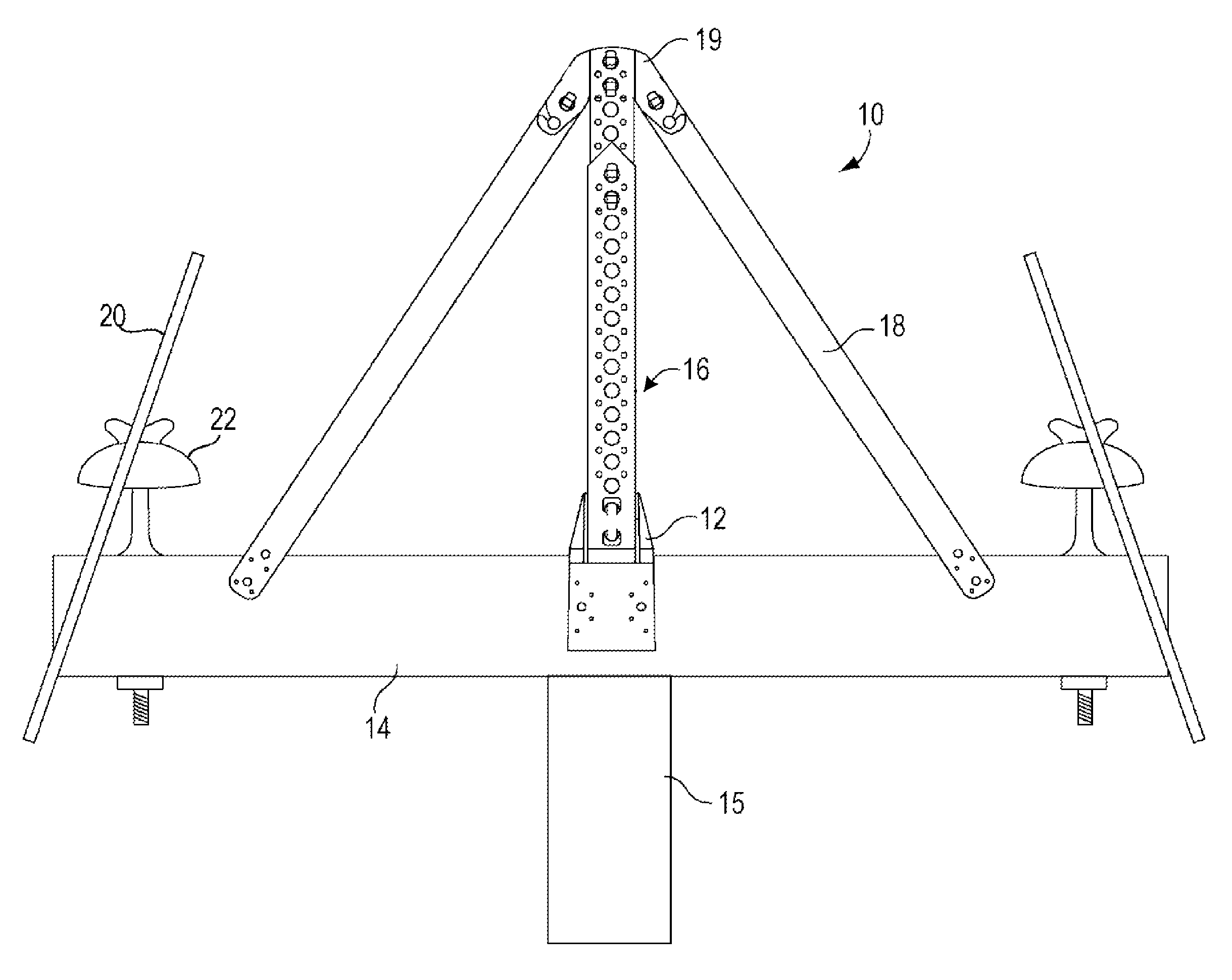
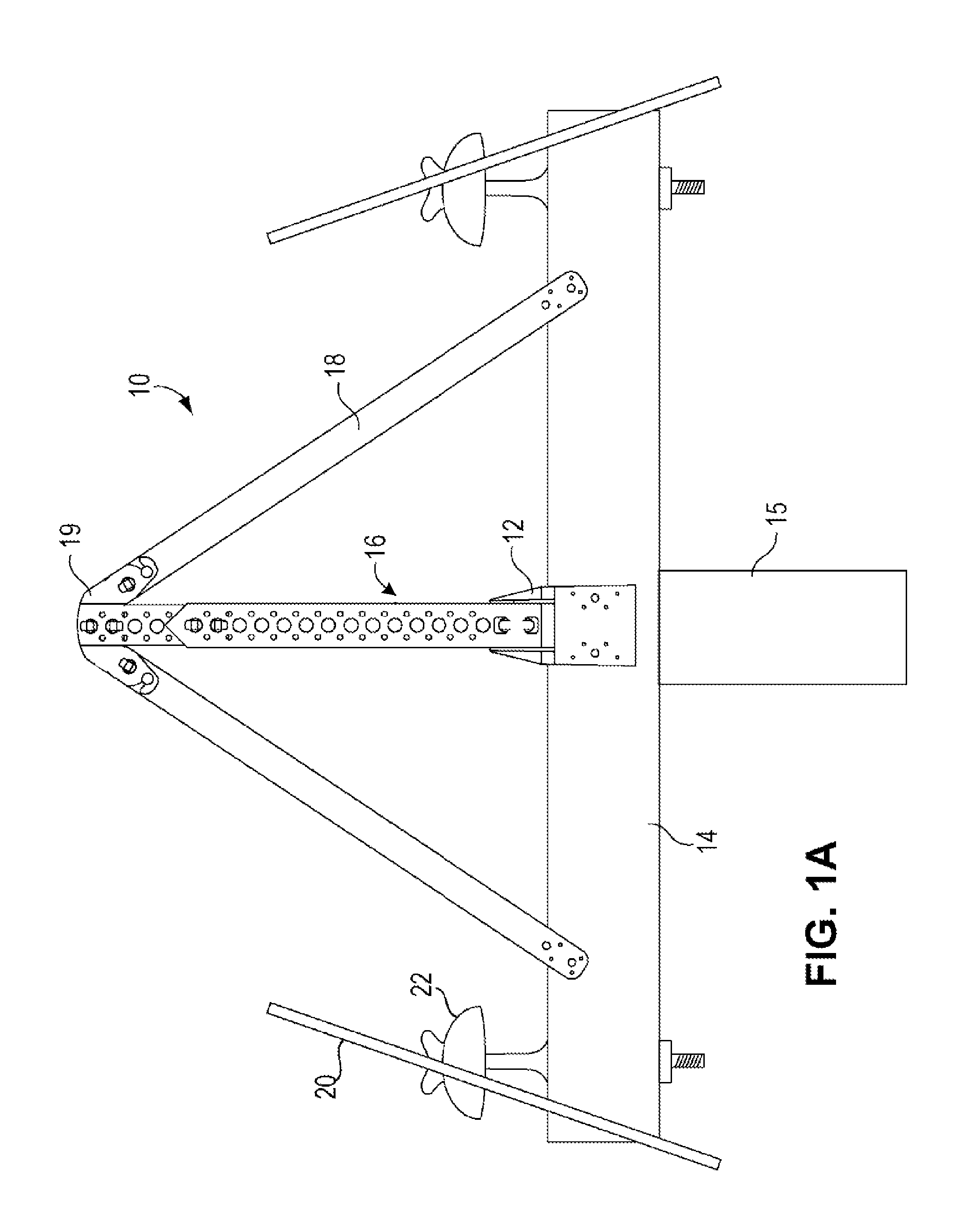
[0050]FIG. 1A illustrates an embodiment of the wildlife deterrent 10 in accordance with one embodiment of the invention. A bracket 12 for the deterrent 10 is nailed or lagged (using a lag screw) to a wooden supporting member 14 of a utility support structure 15. An adjustable-length center support 16 is connected to the bracket 12 by hand-releasable clips (seen in greater detail in FIG. 3). Two arms 18 are connected near the top of the center support 16, via a connector piece 19, by hand-releasable clips (seen in greater detail in FIGS. 6-8). The middle portion of the connector piece 19 is obscured by the top of the center support 16. The entire deterrent10 may be molded plastic, such as one-eighth inch thick PVC or polyethylene. The plastic is of a type that has well-defined dielectric characteristics and long life outdoors.

[0051]The center support 16 has an adjustable length to allow the deterrent 10 to be adapted to different separations between conductors 20. Each conductor 20 i...


PUM


Abstract

A wildlife deterrent for a utility support structure member between two conductors includes a bracket for attachment to the supporting member, a center support piece with a variable height arm connector, and two adjustable arms pivotally attached to the arm connector. No tools are required for the adjustments or attachments. Since the effective lengths of the support and arms are adjustable, either by elongation or using different length parts, the same angle of the arms can be achieved no matter what the separation between the conductors, and the gap between the arms and the conductor can be optimal for both deterrence and flashover prevention. The different pieces forming the deterrent can be selected by the lineman to quickly build an optimal deterrent in the field.

Description

FIELD OF THE INVENTION[0001]This invention relates to a wildlife deterrent for use on an electric transmission and distribution system structure, such as a crossarm, pole, or other supporting structure, to prevent electrocution of birds and other wildlife that complete an electrical path phase to phase or phase to ground.BACKGROUND[0002]Electrical transmission and distribution circuits include conductors supported by grounded support structures such as wooden poles, steel poles, concrete poles, and lattice towers. The support structures are essentially grounded since they are embedded in the earth. Each conductor (or wire) is separated from the grounded structure by an insulator, such as a ceramic insulator. The insulators also provide separation between the conductors (or phases). The phase separation is determined by the circuit voltage, the proximity to ground, and the length of the span.[0003]Insulators are manufactured in various sizes and shapes according to industry standards...

Claims


Application Information

Patent Timeline
Patent Type & Authority Patents(United States)
IPC IPC(8): E04B1/72E04H9/16
CPCA01M29/32H02G7/00
Inventor LYNCH, MICHAEL
Owner ECO ELECTRICAL SYST
Why Eureka
Try Eureka