
Analog pseudo random bit sequence generator

a pseudo random bit sequence and analog technology, applied in oscillator generators, pulse generation with predetermined statistical distributions, instruments, etc., can solve the problems of high cost and complex system, and achieve the effect of reducing circuitry needed

Inactive Publication Date: 2012-04-10
ANRITSU CO
View PDF4 Cites 18 Cited by
  • Summary
  • Abstract
  • Description
  • Claims
  • Application Information

AI Technical Summary

Benefits of technology

"The present invention provides a PRBS generator that can operate at very high frequencies. This is achieved by replacing typical components with microwave components and using delay lines and a mixer / amplifier instead of a conventional EXOR gate. The output of the amplifier is connected back to the delay lines through a power splitter. The invention also suggests using complementary outputs of the EXOR gate to reduce circuitry needed for a high frequency PRBS generator. The technical effect of the invention is to enable high frequency operation of a PRBS generator and reduce circuitry needed for the same."

Problems solved by technology

The disadvantage of this technique is that the system can become very complex and expensive when system frequencies approach the 10's of GHz range.

Method used


Image

  • Analog pseudo random bit sequence generator
  • Analog pseudo random bit sequence generator
  • Analog pseudo random bit sequence generator

Examples


Embodiment Construction

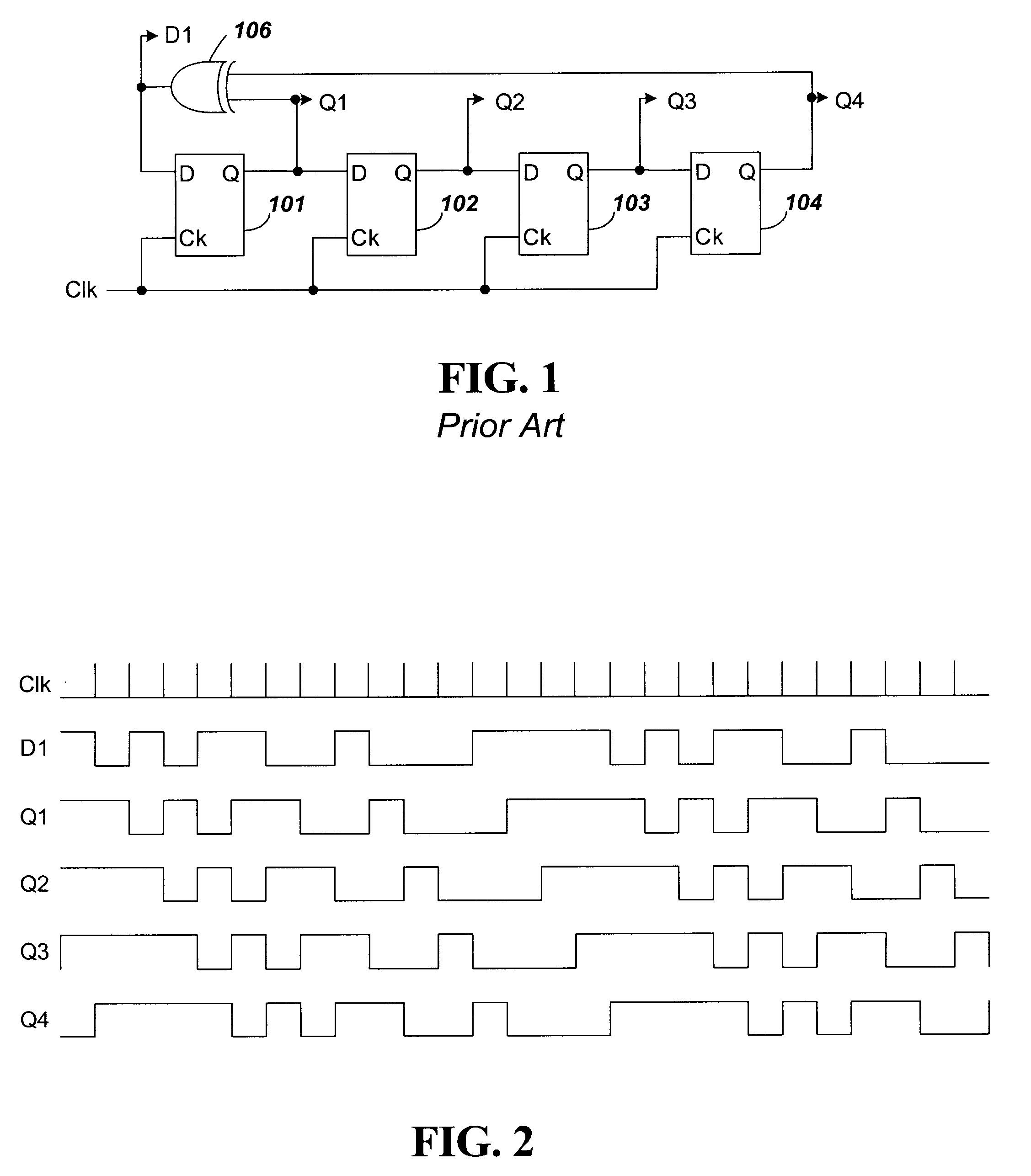
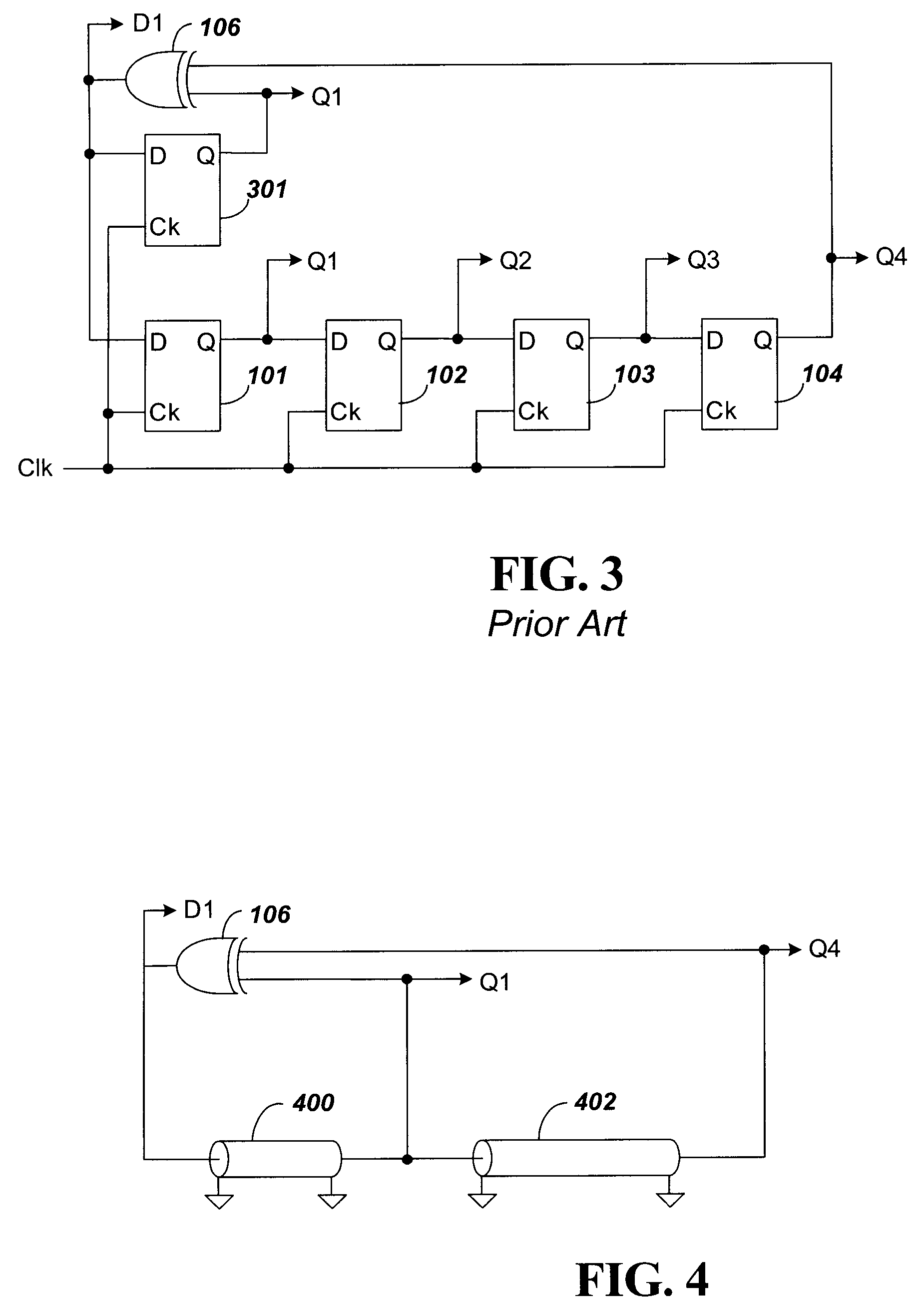
[0031]FIGS. 4 and 5 show circuitry for a high frequency PRBS generator according to embodiments of the present invention. FIG. 4 provides an analog conversion from the digital generator of FIG. 1. FIG. 5 provides an analog conversion from the digital PRBS generator of FIG. 3. The circuit of FIG. 5 corresponds with a majority of the analog PRBS circuits subsequently discussed, which is why the circuit of FIG. 3 is discussed in the background and further herein. The implementations of FIGS. 4 and 5 produce signals D1, Q1 and Q4 with a timing diagram as shown in FIG. 2.

[0032]In FIGS. 4 and 5, delay lines replace the D flip-flops of respective FIGS. 1 and 3. In FIG. 4, a first delay line 400 connects the output of EXOR gate 106 to a first input of the EXOR gate 106. The first input of the EXOR gate 106 is designated as the Q1 tap. A second delay line 402 connects the tap Q1 to a second input of the EXOR gate 106. The second input of the EXOR gate 106 is designated as the Q4 tap. By sele...


PUM


Abstract

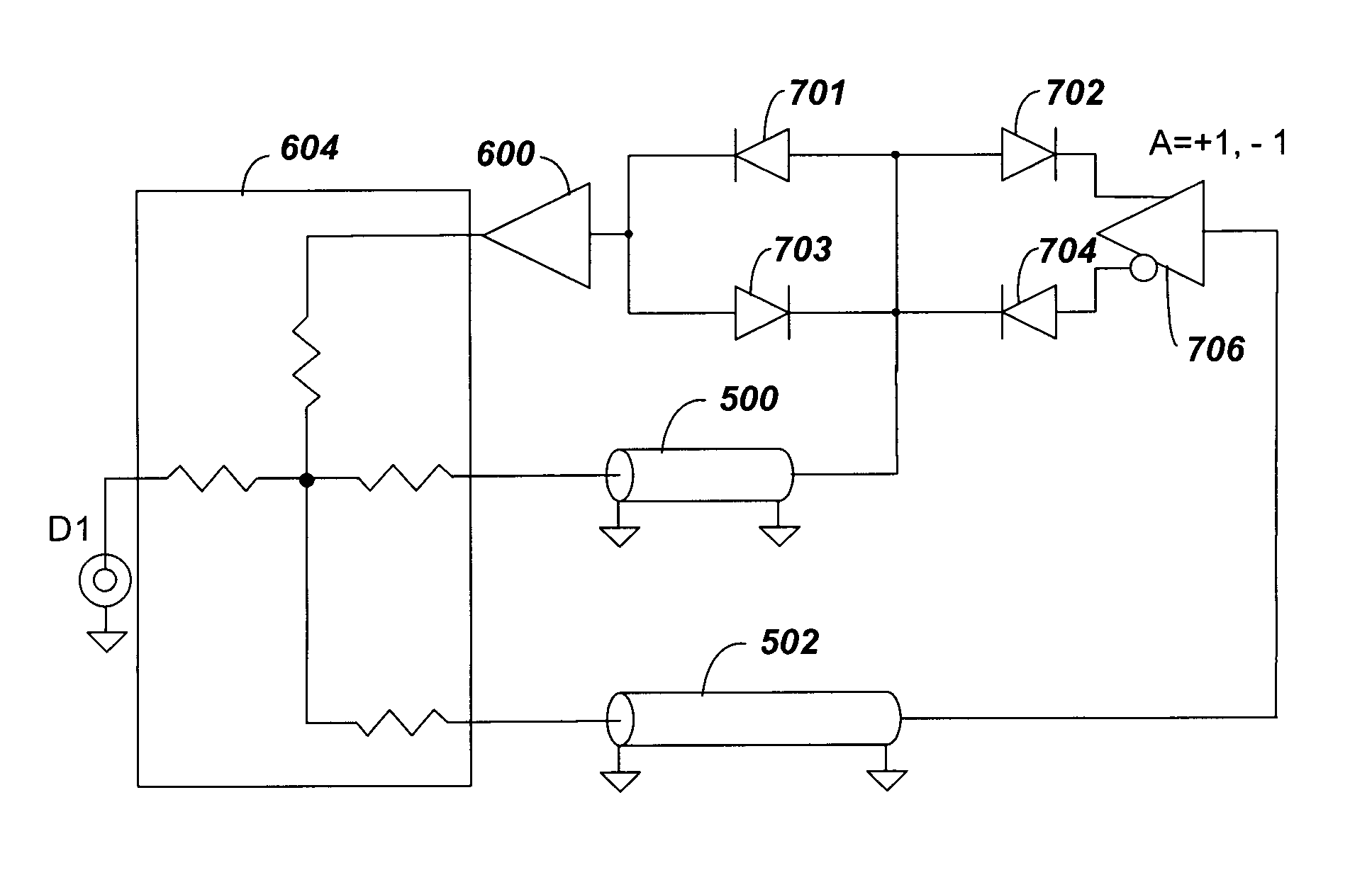
A Pseudo Random Bit Sequence (PRBS) generator is provided with components to enable operation at very high microwave frequencies with inexpensive components. The PRBS generator initially replaces the D flip-flops of a conventional PRBS generator with delay lines connected in a similar manner. Further, an exclusive OR (EXOR) gate used in a conventional device is replaced in one embodiment by a mixer and amplifier. In another embodiment, the EXOR gate is replaced by a Gilbert Cell. In some embodiments, complementary outputs of an EXOR gate are connected to separate delay lines to reduce components needed for the PRBS generator.

Description

BACKGROUND[0001]1. Technical Field[0002]The present invention relates to circuitry for an analog pseudo random bit sequence (PRBS) generator that can be used, for example, to exercise digital circuits using pseudo random patterns. The PRBS generator, in another example, can produce analog noise if fed into a digital circuit.[0003]2. Related Art[0004]FIG. 1 shows a block diagram of prior art digital implementation of a PRBS generator. This PRBS generator is used to exercise digital circuits using pseudo random bit patterns. It can also be used to produce analog noise if fed into a D / A converter. The circuit includes D-type flip-flops or registers 101-104 connected in series, and driven by a common clock signal Clk. Each of the registers 101-104 produces a respective tap output Q1-Q4. The Q1 tap from register 101 provides a first input to Exclusive OR (EXOR) gate 106. The Q4 tap produces a second input to the EXOR gate 106. The output D1 of EXOR gate 106 is provided back to the D inpu...

Claims


Application Information

Patent Timeline
Patent Type & Authority Patents(United States)
IPC IPC(8): G06F1/02
CPCH03K3/84
Inventor BRADLEY, DONALD ANTHONY
Owner ANRITSU CO
Learn More