
Approach for injecting a reductant

a technology of reductant and nitrogen oxide, which is applied in the direction of machines/engines, lighting and heating apparatus, separation processes, etc., can solve the problems of weight and robustness, system undesirable, and reduce the conversion efficiency of nitrogen oxide at the scr catalyst, so as to reduce weight and robustness. concerns

Active Publication Date: 2012-04-03
FORD GLOBAL TECH LLC
View PDF16 Cites 7 Cited by
  • Summary
  • Abstract
  • Description
  • Claims
  • Application Information

AI Technical Summary

Benefits of technology

[0002]Selective catalytic reduction (SCR) systems have been used to reduce automotive emissions. Such systems typically add a gaseous or liquid reductant, such as ammonia or urea, to the exhaust gas stream from an engine to be absorbed onto a catalyst where the reductant reacts with nitrogen oxides in the exhaust gas to form water vapor and nitrogen. However, SCR systems may rely on uniform mixing of the reductant with nitrogen oxides in the exhaust stream upstream of the SCR catalyst. This may lead to various problems. For example, ineffective mixing of urea delivered from an on-board storage device may reduce the conversion efficiency of nitrogen oxides at the SCR catalyst.
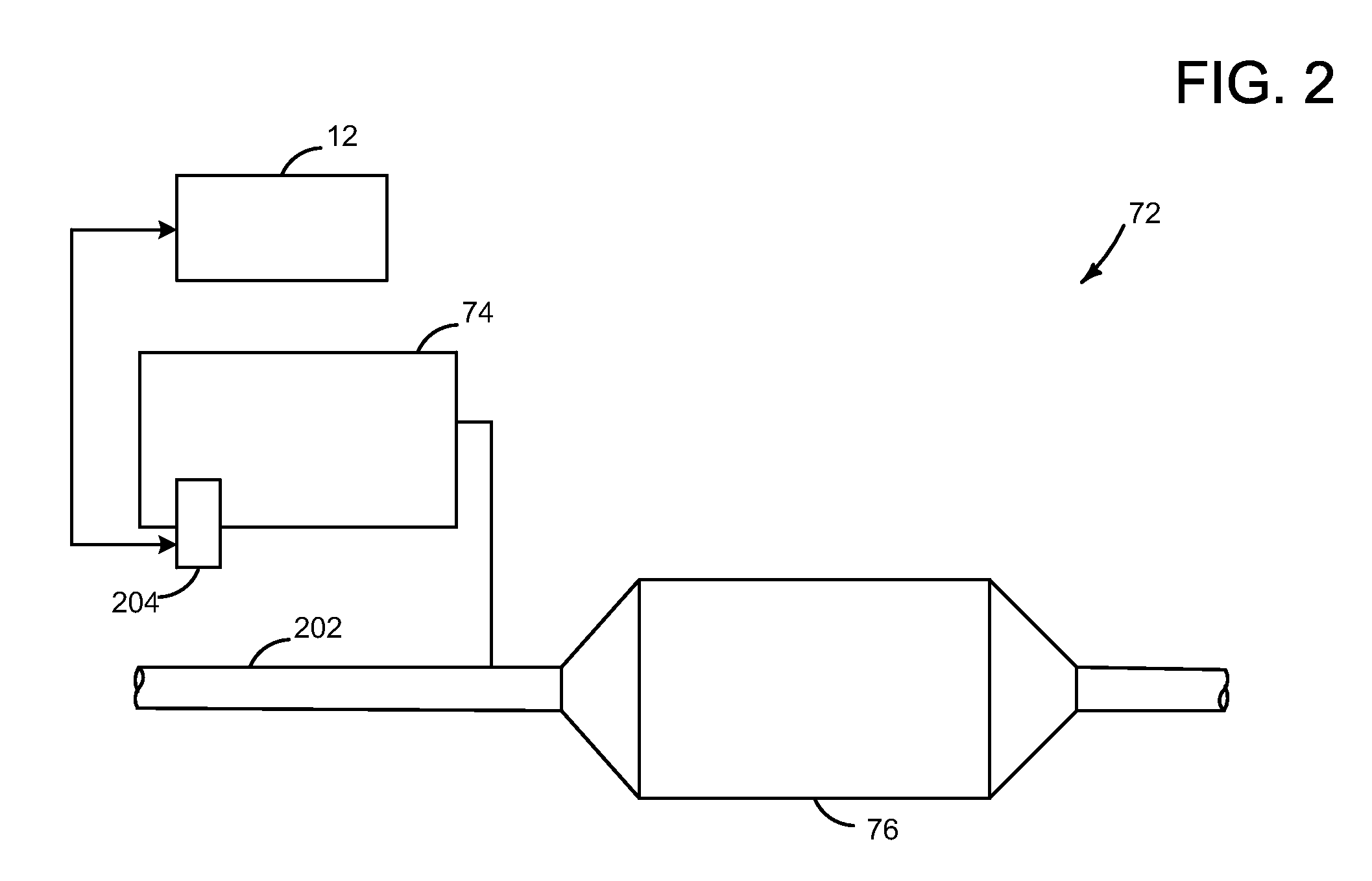
[0004]The inventors herein have realized that these concerns and others may be addressed by applying an ultrasonic field to a reductant-containing liquid in the reductant storage device to generate a mist of the reductant-containing liquid, and selectively introducing an amount of mist to an exhaust system coupled to the catalyst based on an engine operating condition. Such methods of generating and supplying a mist from the reductant may facilitate the delivery of a uniform mixture of reductant and nitrogen oxide and nitrogen dioxide (NOx) to the emission control device with reduced weight and robustness concerns.

Problems solved by technology

This may lead to various problems.
For example, ineffective mixing of urea delivered from an on-board storage device may reduce the conversion efficiency of nitrogen oxides at the SCR catalyst.
However, concerns of equipment weight and robustness against orifice plugging may prove such systems undesirable.

Method used


Image

  • Approach for injecting a reductant
  • Approach for injecting a reductant
  • Approach for injecting a reductant

Examples


Embodiment Construction

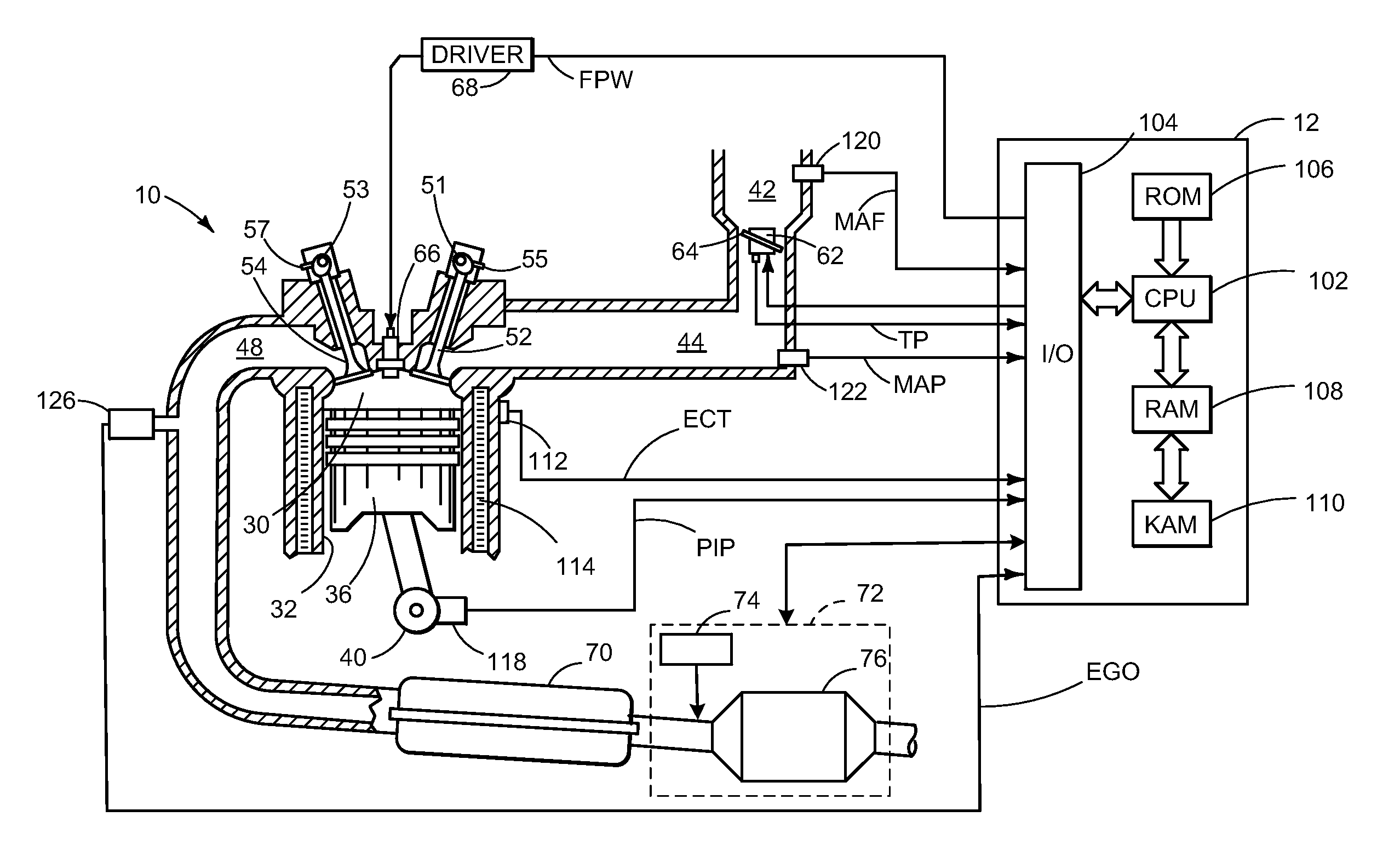
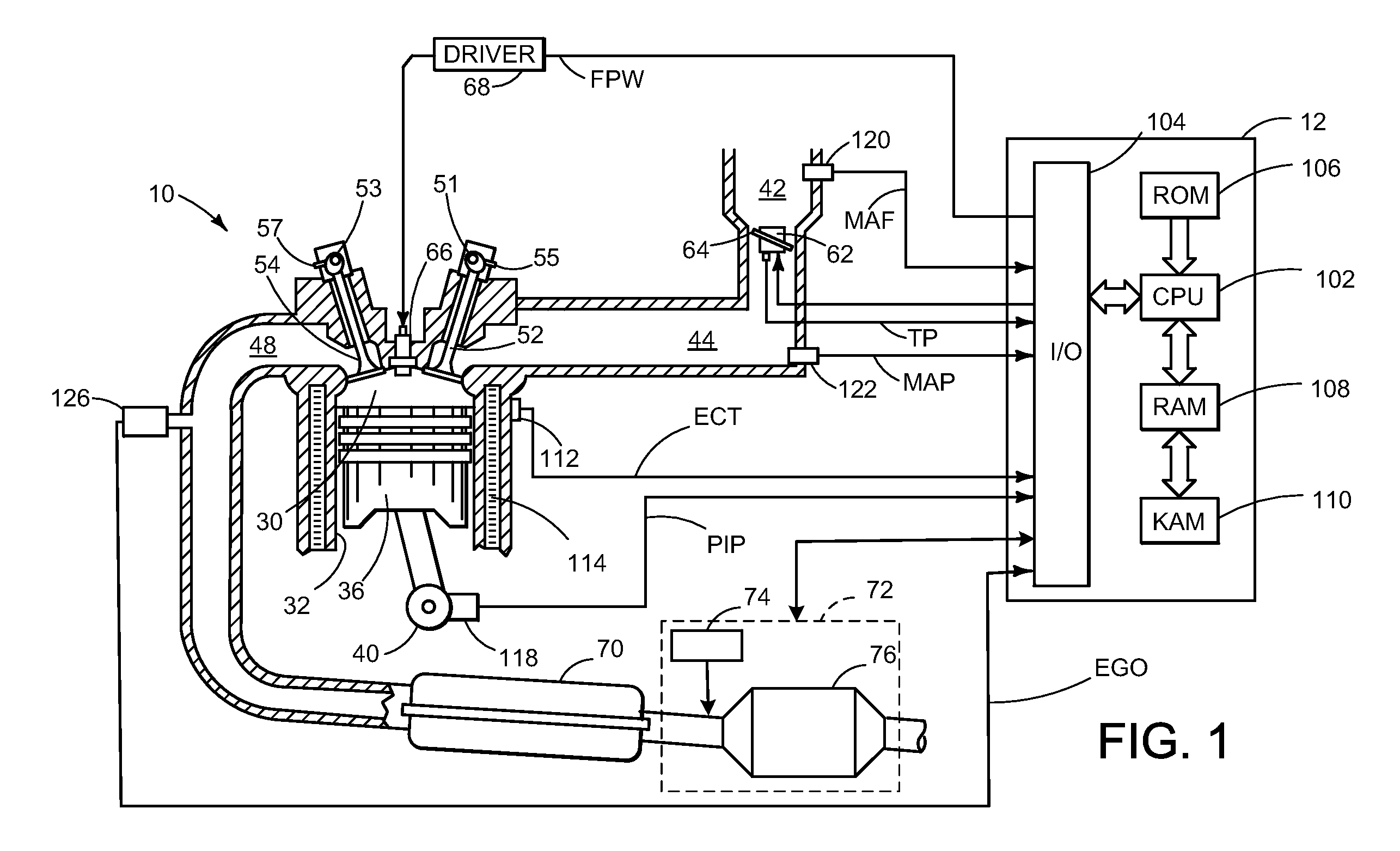
[0008]Referring now to FIG. 1, direct injection internal combustion engine 10, comprising a plurality of combustion chambers and controlled by electronic engine controller 12, is shown. Combustion chamber 30 of engine 10 includes combustion chamber walls 32 with piston 36 positioned therein and connected to crankshaft 40. In one example, piston 36 includes a recess or bowl (not shown) to form selected levels of stratification or homogenization of charges of air and fuel. Alternatively, a flat piston may also be used.

[0009]Combustion chamber 30 is shown communicating with intake manifold 44 and exhaust manifold 48 via intake valve 52, and exhaust valve 54. Fuel injector 66 is shown directly coupled to combustion chamber 30 for delivering liquid fuel directly therein in proportion to the pulse width of signal fpw received from controller 12 via conventional electronic driver 68. Fuel is delivered to fuel system (not shown) including a fuel tank, fuel pumps, and a fuel rail. In some em...


PUM

PropertyMeasurementUnit
ultrasonic fieldaaaaaaaaaa
concentrationaaaaaaaaaa
pressureaaaaaaaaaa

Abstract

A method of operating an internal combustion engine having a reductant delivery and storage system in an emission control system is disclosed. The method comprises applying an ultrasonic field to a reductant-containing liquid in the reductant storage device to generate a mist of the reductant-containing liquid, and selectively introducing an amount of mist to an exhaust system coupled to the catalyst based on an engine operating condition.

Description

TECHNICAL FIELD[0001]The present application relates to the field of automotive emission control systems and methods.BACKGROUND AND SUMMARY[0002]Selective catalytic reduction (SCR) systems have been used to reduce automotive emissions. Such systems typically add a gaseous or liquid reductant, such as ammonia or urea, to the exhaust gas stream from an engine to be absorbed onto a catalyst where the reductant reacts with nitrogen oxides in the exhaust gas to form water vapor and nitrogen. However, SCR systems may rely on uniform mixing of the reductant with nitrogen oxides in the exhaust stream upstream of the SCR catalyst. This may lead to various problems. For example, ineffective mixing of urea delivered from an on-board storage device may reduce the conversion efficiency of nitrogen oxides at the SCR catalyst.[0003]One way to facilitate mixing of urea injects a urea solution directly into the engine exhaust stream. For example, an injector may apply pressure to force the urea solu...

Claims


Application Information

Patent Timeline
Patent Type & Authority Patents(United States)
IPC IPC(8): F01N3/00F01N3/10
CPCB01D53/90B01D53/9431B01D2251/2067B01D2259/816F01N2570/14F01N2610/02F01N2610/1453B01D53/92F01N3/206
Inventor PATTERSON, JOSEPHLAING, PAUL M.
Owner FORD GLOBAL TECH LLC
Learn More