
Real time measurement of shock pressure

a real-time measurement and shock pressure technology, applied in the field of fiber-based optical pressure sensing methods, can solve the problems of spurious voltages affecting the measurement, the sensor element exposed to the shock must be inexpensive, and the electrical connection and wires are awkward for some applications, so as to reduce the band gap, the response time is fast enough, and the effect of less invasiveness

Inactive Publication Date: 2012-03-13
THE UNITED STATES AS REPRESENTED BY THE DEPARTMENT OF ENERGY
View PDF10 Cites 15 Cited by
  • Summary
  • Abstract
  • Description
  • Claims
  • Application Information

AI Technical Summary

Benefits of technology

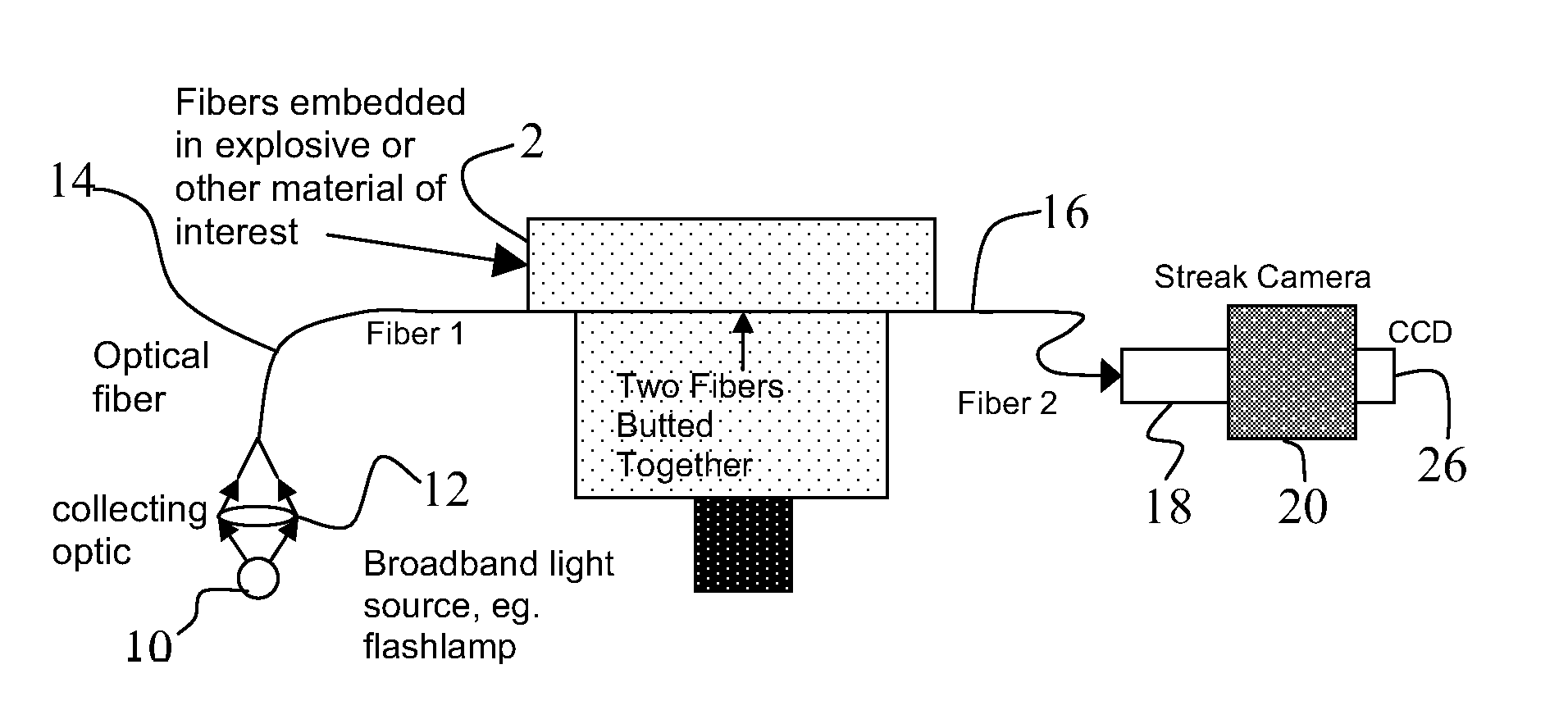
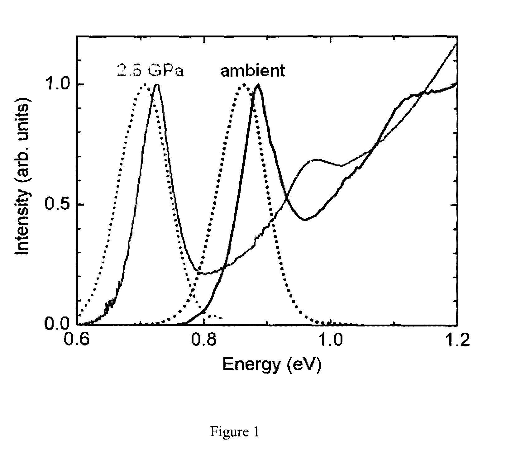
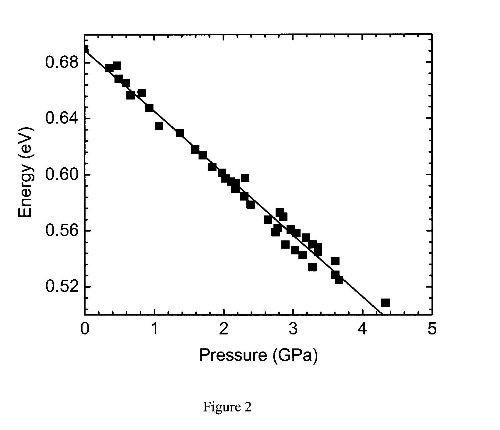
[0011]A fiber-based optical pressure-sensor, made using semiconductor nanocrystal quantum dots (NQDs) as the active transducing material, provides response time fast enough for shock wave measurements. The application of high pressures to many common bulk semiconductors causes a large change in the size of the band gap, as observed by optical absorbance or by conductance measurements. For example, PbSe NQDs show a strong reduction of the band gap with application of static pressure. For NQDs, the shift in band gap can be observed as a shift of the PL peak. Fiber-based, optical pressure-sensing methods would allow one to replace wires with smaller, less invasive and less conducting fibers made of glass or other transparent materials.

Problems solved by technology

In addition, because shock waves often involve high ultimate pressures that often destroy the sensor, the sensor element exposed to the shock must be inexpensive.
Piezo-electric, piezo-resistive and electrical pin gauges are the most commonly used sensors for many shock experiments, but they all require electrical connections and wires which are awkward for some applications.
In addition, fast movement of the wires as a result of the shock can cause spurious voltages that compromise the measurement.
Finally, the wires themselves are an intrusive, complicating factor, as they can conduct heat out of the system, and can change the density and shock velocity profile of the system substantially, perturbing many types of coincident measurements of interest.
Ruby fluorescence, however, takes place on the order of several microseconds, and becomes even slower as pressure increases, too slow to be useful for many shock measurement systems.
Thus, it requires either long measurement times, or extremely powerful and difficult to use laser light sources.

Method used


Image

  • Real time measurement of shock pressure
  • Real time measurement of shock pressure
  • Real time measurement of shock pressure

Examples


Embodiment Construction

[0026]The invention is a fiber-based optical pressure-sensor, with response time fast enough for shock wave measurements, made using semiconductor nanocrystal quantum dots (NQDs) as the active transducing material. NQDs are very small particles of semiconductor material on the order of nanometers in size, which have unique properties due to quantum confinement effects. Most NQDs made of common semiconductor materials, such as II-VI, III-V, IV-VI and Group IV materials, demonstrate bright, size-tunable photoluminescence (PL), or fluorescence. As such, they are the subjects of current investigations for applications ranging from LEDs and lasers, to sensors and bio-labels.

[0027]The application of high pressures to many common bulk semiconductors causes a large change in the size of the band gap, as observed by optical absorbance or by conductance measurements. The present inventors have recently demonstrated that PbSe NQDs show a strong reduction of the band gap with application of sta...


PUM


Abstract

A fiber-based optical pressure-sensor, made using semiconductor nanocrystal quantum dots (NQDs) as the active transducing material, provides response time fast enough for shock wave measurements. For NQDs, the shift in band gap as a result of applied pressure can be observed as a shift of the photoluminescence (PL) peak. Further, the shift of the principal absorbance feature allows pressure measurements faster than those obtainable by following the PL peak.

Description

[0001]The United States Government has rights in this invention pursuant to Contract No. DE-AC52-06NA25396 between the United States Department National Nuclear Security Administration and the Los Alamos National Security LLC for the operation of the Los Alamos National Laboratory.BACKGROUND OF THE INVENTION[0002]1. Field of the Invention[0003]The present invention relates to techniques for measuring shock pressure, and more specifically, it relates to fiber-based, optical pressure-sensing methods.[0004]2. Description of Related Art[0005]Shock waves are pressure waves with a very short rise time, and are produced in both impact and explosive phenomena. Dynamic experiments with shock waves require a tool to measure relatively large, rapid pressure changes.[0006]A desirable shock pressure sensor would offer fast (sub-microsecond) response, a large dynamic range, and a non-perturbing interface that is easily adaptable to a variety of systems to be studied. In addition, because shock wa...

Claims


Application Information

Patent Timeline
Patent Type & Authority Patents(United States)
IPC IPC(8): G02B6/00
CPCG01L1/242G01L5/14G01L11/025
Inventor SANDER, ROBERT K.ZHURAVLEV, KIRILL K.SCHALLER, RICHARD D.PIETRYGA, JEFFREY M.WHITEHEAD, MICHAEL
Owner THE UNITED STATES AS REPRESENTED BY THE DEPARTMENT OF ENERGY
Learn More