
A rail transit monitoring system and method

A monitoring system and rail transit technology, applied in the field of rail transit, can solve problems that affect the accuracy of obstacle detection, train running speed is fast, and foreign objects cannot be detected, so as to improve operation efficiency and fault handling efficiency, improve train driving safety, The effect of improving train safety

Active Publication Date: 2022-04-01
成都希格玛光电科技有限公司
View PDF11 Cites 0 Cited by
  • Summary
  • Abstract
  • Description
  • Claims
  • Application Information

AI Technical Summary

Problems solved by technology

It has the following disadvantages: it can only control the blocked area of ​​the train, but cannot detect foreign objects that suddenly enter the track area, such as pedestrians, equipment falling, landslides, etc.; at the same time, when the signal system fails and the ATP system is cut off, the vehicle The driving can only rely on the driver's manual driving and manual lookout, which often leads to major accidents
[0003] In order to make up for the inability to detect foreign objects intruding into the track area in real time in automatic rail transit automatic driving technology, in the existing technology, an image acquisition module is installed on the train to collect real-time images of the track in front of the train, and at the same time, millimeter-wave radar is added As the distance extension of obstacle detection, it achieves the purpose of replacing the ATP system. However, due to the complex operating environment of the rail train and the high speed of the train, it is impossible to accurately detect the invasion of foreign objects. For example, in the tunnel, due to the small turning radius, the image cannot be far away. Distance observation, rapid changes in ambient light conditions, affect the accuracy of obstacle detection

Method used


Image

  • A rail transit monitoring system and method
  • A rail transit monitoring system and method
  • A rail transit monitoring system and method

Examples


Embodiment Construction

[0037] Embodiments of the present invention are described in detail below, examples of which are shown in the drawings, wherein the same or similar reference numerals designate the same or similar elements or elements having the same or similar functions throughout. The embodiments described below by referring to the figures are exemplary only for explaining the present invention and should not be construed as limiting the present invention.

[0038] In the description of the present invention, unless otherwise specified and limited, it should be noted that the terms "installation", "connection" and "connection" should be understood in a broad sense, for example, it can be mechanical connection or electrical connection, or two The internal communication of each element may be directly connected or indirectly connected through an intermediary. Those skilled in the art can understand the specific meanings of the above terms according to specific situations.

[0039] The inventio...


PUM


Abstract

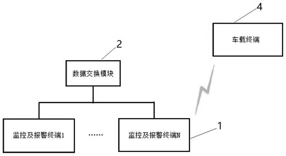
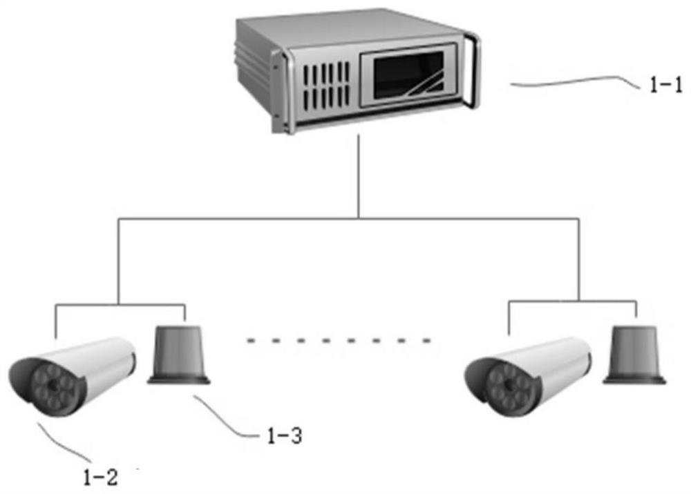
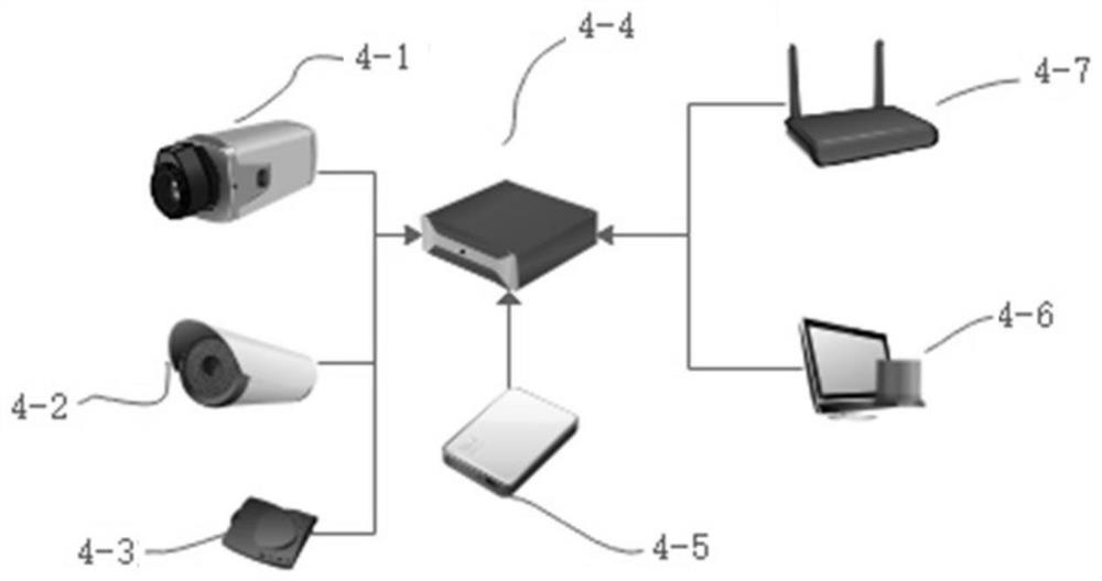
The invention provides a rail traffic monitoring system and method. It includes multiple monitoring and alarm terminals, data exchange modules and vehicle-mounted terminals arranged along the track; the monitoring and alarm terminal includes multiple image acquisition modules, multiple optical alarm modules, and the first processing module; all first processing modules are connected and communicated through the data exchange module The first processing module identifies whether there is a foreign object in the image output by the image acquisition module, and when there is a foreign object intrusion, the first processing module of the monitoring and alarm terminal at the front or the rear transmits an alarm signal, so that the first distance range at the front or the rear The optical alarm module in the vehicle sends out an optical alarm signal; the vehicle-mounted terminal includes an optical receiver located at the front of the train and a second processing module. The system sends out an optical alarm signal through the optical alarm module, and does not rely on the signal system to transmit the alarm signal. When the signal communication system fails, or in scenarios with poor communication quality such as tunnels, the alarm signal can still be effectively transmitted to improve driving safety.

Description

technical field [0001] The invention relates to the field of rail transit, in particular to a rail transit monitoring system and method. Background technique [0002] In the automatic driving technology of rail transit, the safety of the train is realized by automatic train protection system (Automatic Train Protection, referred to as: ATP). The ATP system consists of trackside equipment for automatic train protection, on-board equipment and interlocking equipment in the control area. It has the following disadvantages: it can only control the blocked area of ​​the train, but cannot detect foreign objects that suddenly enter the track area, such as pedestrians, equipment falling, landslides, etc.; at the same time, when the signal system fails and the ATP system is cut off, the vehicle The driving can only rely on the driver's manual driving and artificial lookout, which often leads to larger accidents. [0003] In order to make up for the inability to detect foreign objec...

Claims


Application Information

Patent Timeline
Patent Type & Authority Patents(China)
IPC IPC(8): B61L23/04
CPCB61L23/041
Inventor 赵波邹泽亚李祥
Owner 成都希格玛光电科技有限公司
Learn More