
Method and a device for separating of magnetic and non-magnetic blanks placed in a stack

a technology of magnetic and non-magnetic blanks, applied in the direction of stack separation, metal-working feeding devices, positioning devices, etc., can solve the problems of inability to use tolerably, quality problems of finished products, and inability to use separating magnets on magnetic materials, etc., to achieve safe and effective separating of magnetic materials, the effect of cheap and simple manufacturing

Active Publication Date: 2012-02-07
BENGTSSON BRODDE
View PDF16 Cites 0 Cited by
  • Summary
  • Abstract
  • Description
  • Claims
  • Application Information

AI Technical Summary

Benefits of technology

[0005]The object of the present invention is to provide a separating device, which in an excellent way fulfils its purpose at the same time as it besides is both cheap and simple to manufacture. Another object of the present invention is also to provide a method for a safe and effective separating of magnetic and non magnetic blanks of sheet e.g. aluminum piece by piece from a stack of blanks with that demand that the method is not limited to mainly quadratic and rectangular blanks having parallel opposite areas, but can also handle that during the last years increased use of form cut blanks. Besides the claim of compactness exists, so that a small space need can be met at the same time as the separating device does not have any physical portions which extend below that level on which the stack of blanks are placed upon. This gives the blank separating device further a very much valuable and unique quality i.e. it has also as one of the main purposes to be available during modifying older, existing equipments constructed only for separating magnetic and more or less quadratic blanks, so that they can manage also non magnetic form cut blanks also if that plane, which the stack of blanks is placed upon is larger than the plane of the stack of blanks, which is not allowed to be any obstacle for grasping of the blanks after said reconstruction.
[0006]Another fundamental object of the invention is to prevent that slipping starts or that the mechanical grasping of the uppermost blank looses its grasp, so that chips are formed or that small particles are loosen from the blank when it shall be separated. This is solved by this invention by an unique trigonometry, which is adjusting the grasping of the teeth in relation to that force which is needed to separate and lift the uppermost blank of the blank stack. Another object of the invention is to provide a simple and robust structure, which is the reason for that a continuous operation can be realized during long periods of time and that the costs are kept within acceptable limits.
[0007]By these features a good separating can be made by a moving means to separate piece by piece and to lift up one or more edges of blanks, which also comprise non magnetic and form cut blanks, by aid of teeth or spines and when needed the device can shoot in an air beam in order to eliminate that vacuum which can exist between the two uppermost blanks. The blank separators can also by their compact design, as mentioned above, be used during reconstruction of existing equipment, which gives considerable cost savings.

Problems solved by technology

Separating magnets can only be used on magnetic materials and cannot be used on non-magnetic materials or blanks.
Wide screw formed arrangements require large planar and parallel opposite areas and therefore can only tolerably be used on quadratic and rectangular blanks and are already of this reason useless on formation cut blanks.
These arrangements are also space requiring when the screws drive the blanks laterally, so that space requiring holding up tools must be installed in order to stop this.
It also required a space much below the separating level, which creates problems when the blank pallets often are larger than these blanks, which are stacked on the pallet.
These screw formed arrangements consist of threads or thread similar grooves, which do not grasp the blank but the blank slips in the threads, which often create not wanted chips on the blanks, which causes quality problems of the finished product.
By that fact that aluminum oxide also wears very hard on these thread groves and which requires frequent and expensive exchanges and besides causes production stops to a cost which is far too much, this method is not useable under production like forms in a modern production.

Method used


Image

  • Method and a device for separating of magnetic and non-magnetic blanks placed in a stack
  • Method and a device for separating of magnetic and non-magnetic blanks placed in a stack
  • Method and a device for separating of magnetic and non-magnetic blanks placed in a stack

Examples


Embodiment Construction

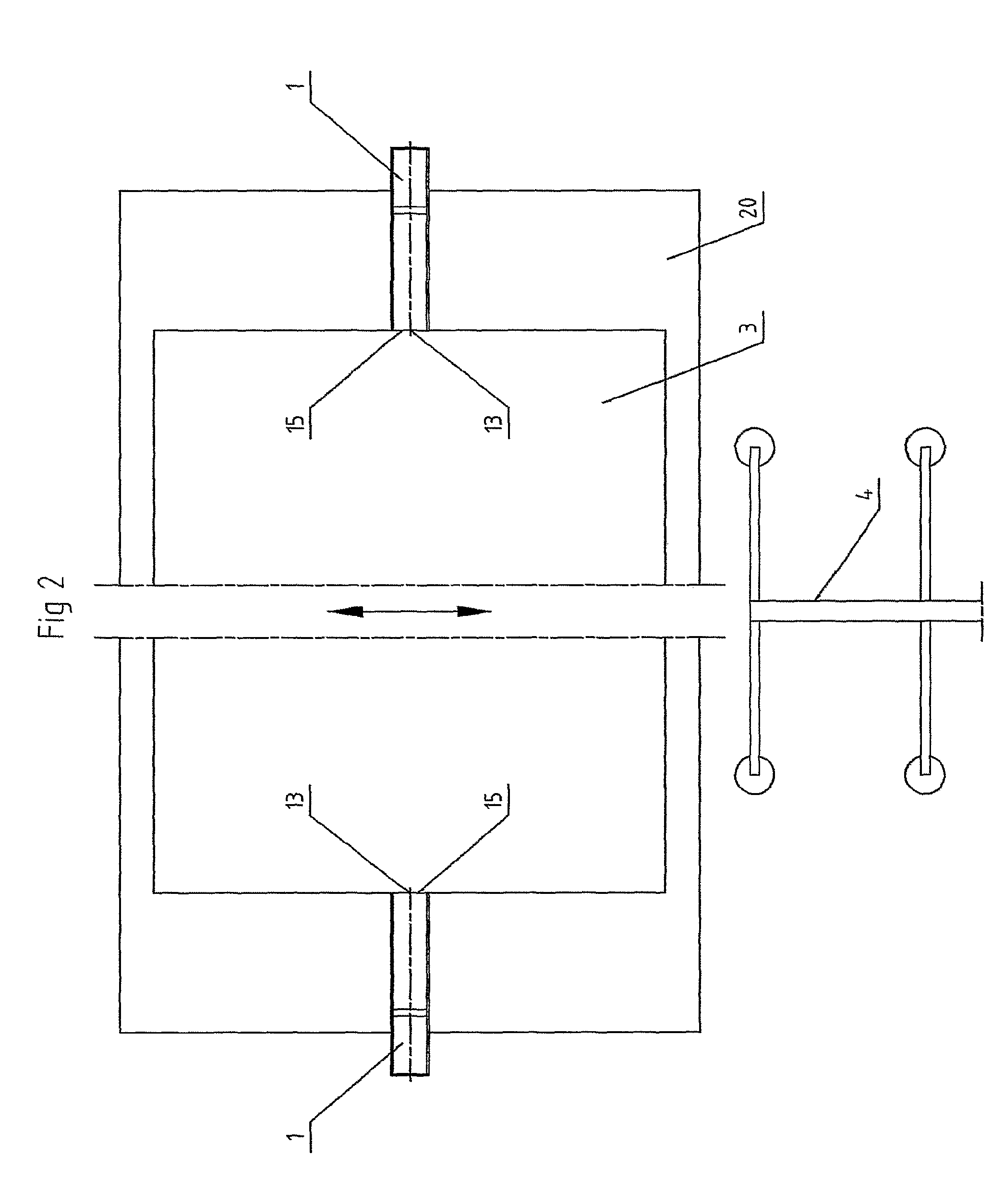
[0019]As can be seen from the drawings the invention consists of at least blank separator or separating unit 1 and in the illustrated example of two separating units 1, contacting against an upper edge portion of that stack 2 of blanks 3, which shall be separated from each other, so that by this adherence between the objects, caused by vacuum, oil film or by other reasons, is stopped, so that the upper most blank in the stack 2 can be caught by a picking means 4 for feeding the blanks into a following machine not illustrated in the drawings. An intended separating direction 5 is parallel to or mainly parallel to a normal to the extension plane of the blanks 3.

[0020]FIG. 8 shows an end view illustrated from the blank stack. From this is evident that the free end or edge of a separating arm 10 comprises at least one friction surface and which in the example illustrated consists of a narrow blade 13 provided with teeth or point projections, the blade having a thickness of approximately...


PUM


Abstract

The invention relates to a method and a device to separate blanks form each other in a stack by that at least one separating unit is brought into contact with one or more of the edges of the blank stack. The separating unit comprises a separating arm having a narrow teeth provided blade, which moves first horizontally until a tooth grasps the uppermost blank, whereupon the arm having the narrow teeth provided blade controllably moves upwards and lifts one blank edge. An air knife, which acts towards the side of the blank stack in a direct connection to the point of application of the teeth provided blade, can give one or several air thrusts when the blade is starting its controlled movement upwards and is urging like an wedge in under a slit under the uppermost blank of the blank stack, an eventual existing vacuum between the blanks being disappeared at the same time as the uppermost blank of the blank stack receives a lifting force by the air cushion, created.

Description

CROSS REFERENCE TO RELATED APPLICATIONS[0001]The present application is a 35 U.S.C. §371 National Phase conversion of PCT / SE2007 / 000838, filed Sep. 24, 2007, which claims benefit of Swedish Application No. 0602004-4, filed Sep. 27, 2006, the disclosure of which is incorporated herein by reference. The PCT International Application was published in the English language.BACKGROUND OF THE INVENTION[0002]The present invention refers to a method and a device for separating magnetic and non-magnetic mainly plane sheet- or disc-shaped blanks piece by piece, such as plates of steel and aluminum, which constitute a stack and other plane blanks e.g. sheets of plastic and so on, which are piled up in similar stacks and which usually are placed on a pallet or rack. The invention comprises a movement means in order to separate piece by piece and lift up one or more edges of these blanks by aid of a separating unit, which is gripping the edge of the uppermost blank and when needed the movement me...

Claims


Application Information

Patent Timeline
Patent Type & Authority Patents(United States)
IPC IPC(8): B65H3/00B65H3/24B65H1/08
CPCB21D43/20B65H3/56B65H3/24B21D43/24B65G59/023B65G59/026B65H3/32B65H3/48
Inventor BENGTSSON, BRODDE
Owner BENGTSSON BRODDE
Learn More