
Liquid crystal display

a liquid crystal display and display technology, applied in non-linear optics, instruments, optics, etc., can solve the problems of reducing contrast performance, reducing numerical aperture of pixels, and light leakage, so as to prevent light leakage, avoid depolarization problems, and prevent depolarization

Active Publication Date: 2012-01-10
JAPAN DISPLAY WEST
View PDF9 Cites 3 Cited by
  • Summary
  • Abstract
  • Description
  • Claims
  • Application Information

AI Technical Summary

Benefits of technology

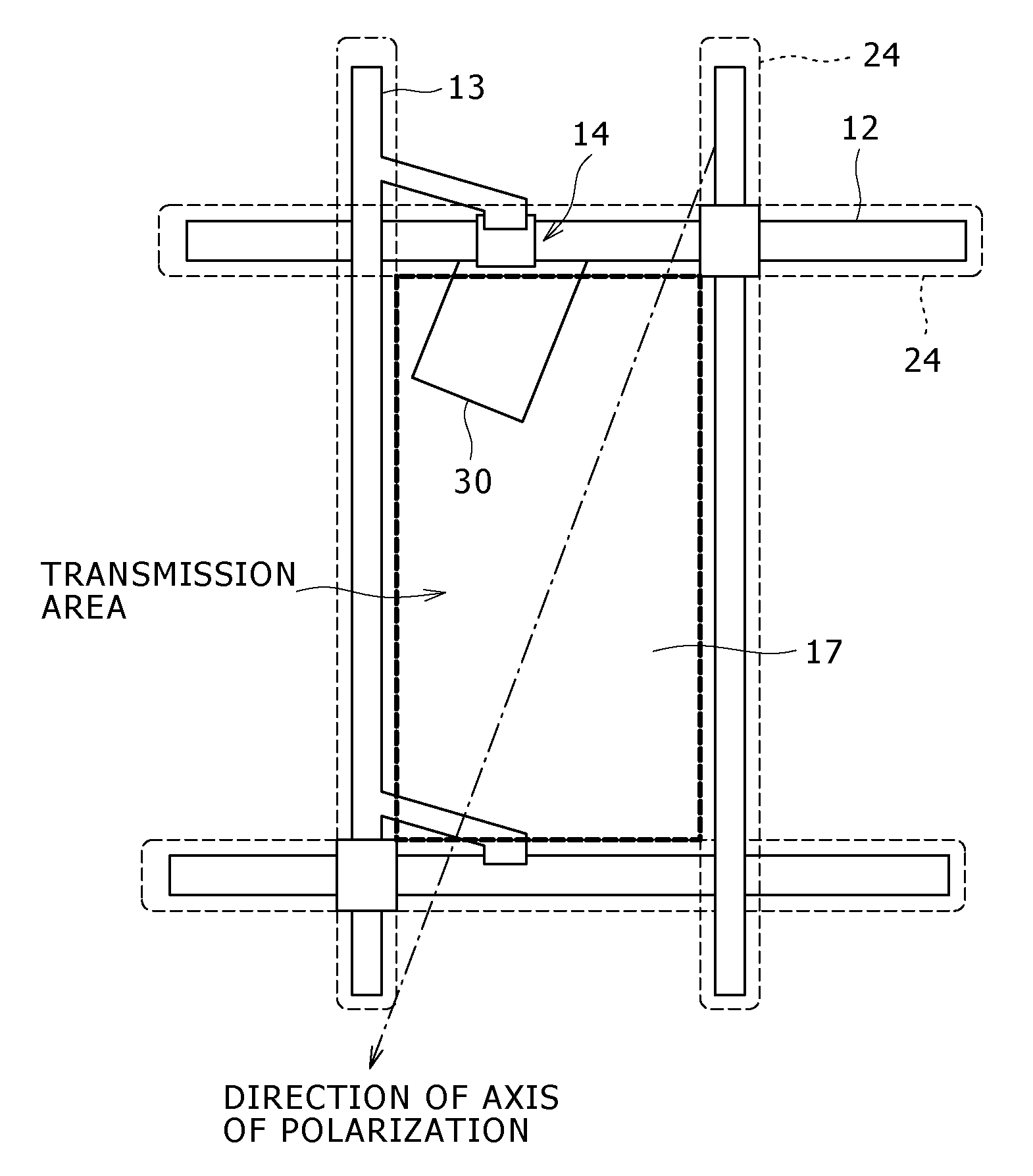
"The present invention provides a liquid crystal display that can effectively restrain the leakage of light caused by depolarization, without sacrificing the numerical aperture of pixels. The display includes a polarizing plate with an axis of linear polarization set in a slanted direction, relative to the horizontal direction of the screen. This slanted direction of the polarization plate helps to prevent interference with the viewer's polarizing sunglasses and ensures proper viewing of the screen. Additionally, the invention provides a method for reducing depolarization at the edge parts of metallic wires in the transmission areas, by shaping the end part of the wire in a slanted direction."

Problems solved by technology

However, in the case where the axis of linear polarization and an end surface of the metallic wire are mutually slanted (oblique), the linearly polarized light reflected and diffracted at the end surface is disturbed in polarization state, resulting in leakage of light.
Since the leakage of light causes a lowering in contrast performance of the liquid crystal display, a countermeasure against it has to be taken.
However, the black mask restricts the effective area (aperture area) of each of the transmission areas, thereby lowering the numerical aperture of the pixels.
Furthermore, where the liquid crystal display is configured taking into account the registration errors in stacking the metallic wires and the black masks, as in Japanese Patent Laid-open No.
This approach, however, leads to a raised manufacturing cost and a lowered transmittance.

Method used


Image

  • Liquid crystal display
  • Liquid crystal display
  • Liquid crystal display

Examples


Embodiment Construction

[0022]Now, embodiments of the liquid crystal display pertaining to the present invention will be described in detail below referring to the drawings. FIGS. 1A and 1B schematically illustrate a first embodiment of the liquid crystal display pertaining to the present invention, in which FIG. 1A illustrates the overall sectional structure of the liquid crystal display, and FIG. 1B is a schematic plan view of a structure corresponding to one pixel.

[0023]As shown in FIG. 1A, the liquid crystal display includes a pair of substrates 1 and 1a, a liquid crystal 10 held therebetween, and a polarizing plate 21 disposed on the side of one of the substrates 1. The polarizing plate 21 converts externally coming incident light into linearly polarized light. In this embodiment, the liquid crystal display is of the transmission type in which a backlight 23 is provided. The polarizing plate 21 converts illuminating light emitted from the backlight 23 into linearly polarized light. The liquid crystal ...


PUM

PropertyMeasurementUnit
transparentaaaaaaaaaa
voltageaaaaaaaaaa
areaaaaaaaaaaa

Abstract

A liquid crystal display including a polarizing plate having a linear polarization axis slanted in relation to a scan line, a transparent pixel electrode, an active element which drives the transparent pixel electrode, and a wire for connecting the active element and the transparent pixel electrode. The wire has an end part so shaped as to be slanted in a direction parallel to or perpendicular to the linear polarization axis.

Description

BACKGROUND OF THE INVENTION[0001]1. Field of the Invention[0002]The present invention relates to a liquid crystal display. More particularly, the present invention relates to a technology for restraining leakage of light from a transmission type liquid crystal display.[0003]2. Description of the Related Art[0004]A transmission type liquid crystal display ordinarily includes a pair of substrates, a liquid crystal held between the substrates, and a polarizing plate disposed at least on the side of one of the substrates. The polarizing plate converts incident light, coming externally (for instance, from an illuminating backlight), into linearly polarized light. The liquid crystal controls the transmission condition of the linearly polarized light according to a voltage, to thereby display an image.[0005]In the case of a liquid crystal display of the active matrix type, the substrate on one side has scan lines, signal lines, and pixels disposed in locations where the scan lines and the ...

Claims


Application Information

Patent Timeline
Patent Type & Authority Patents(United States)
IPC IPC(8): G02F1/1343
CPCG02F1/134363G02F1/136286G02F1/1335G02F1/1343G02F1/136
Inventor OGURA, KENJITATEMORI, SHUICHI
Owner JAPAN DISPLAY WEST
Learn More