Data reproducing apparatus for improving data recording efficiency
a data recording and reproducing technology, applied in the field of data recording and reproducing apparatus, can solve the problems of reducing the data storage area which can be used effectively, and the data recording efficiency is reduced, so as to improve the data recording efficiency of a recording medium, and suppress the increase of the pad
- Summary
- Abstract
- Description
- Claims
- Application Information
AI Technical Summary
Benefits of technology
Problems solved by technology
Method used
Image

Examples
first embodiment
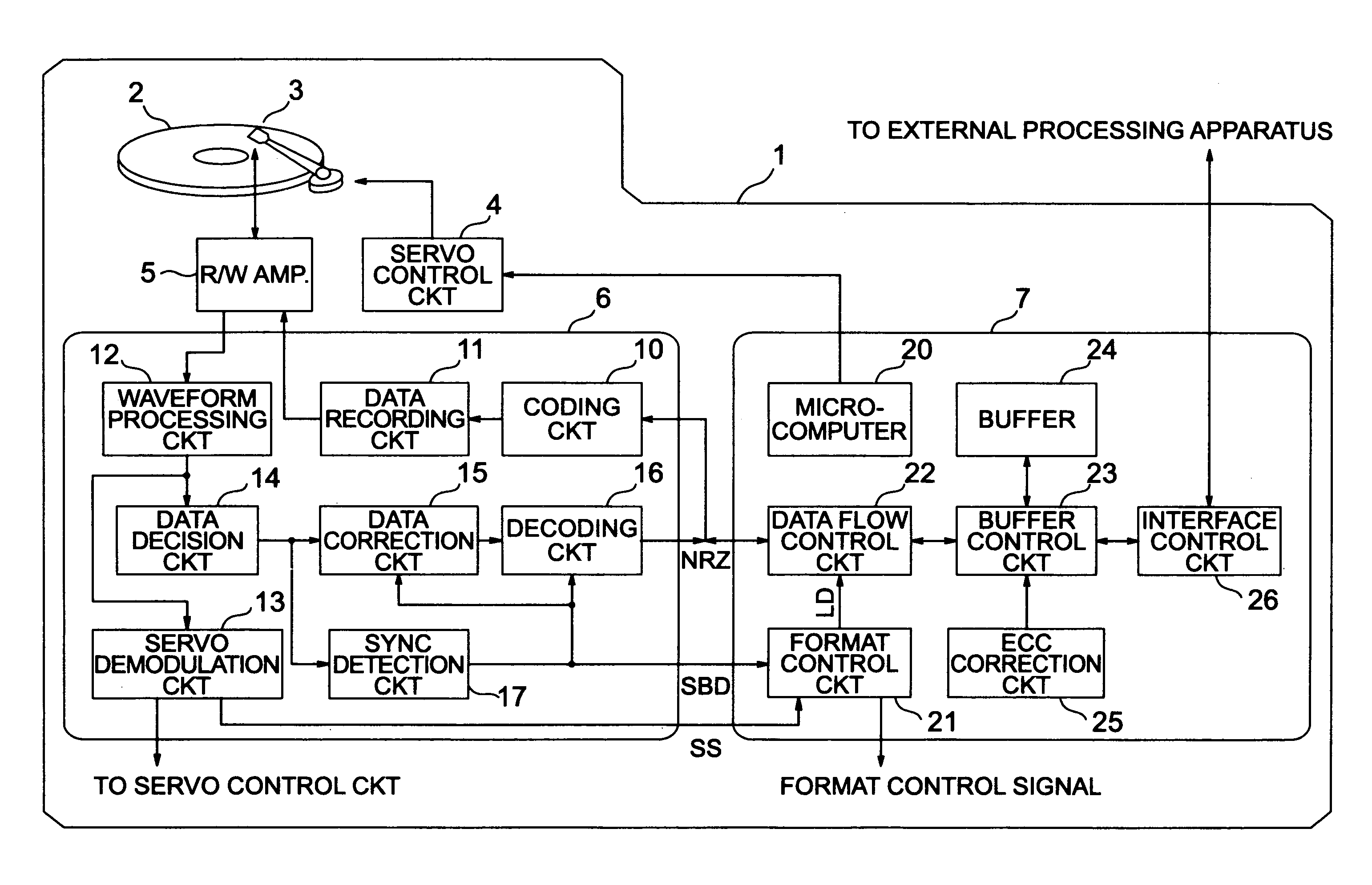
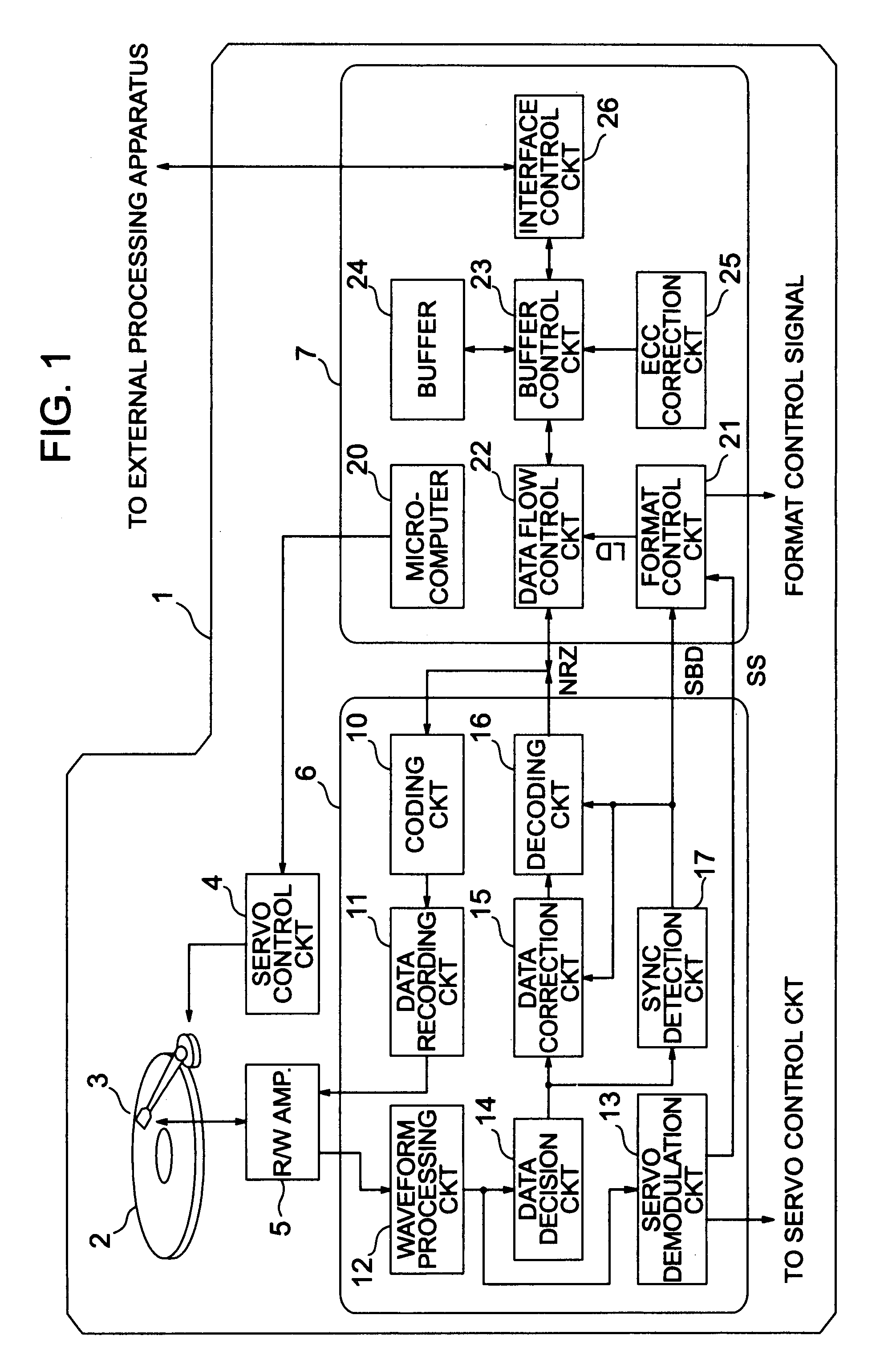
[0052]FIG. 1 schematically illustrates a magnetic disk apparatus according to a first embodiment of the present invention.
[0053]The magnetic disk apparatus 1 includes a magnetic disk 2, a recording and reproducing head 3 for converting magnetic information recorded on the magnetic disk 2 into an electric signal, a servo control circuit 4 for controlling to position the recording and reproducing head 3, an R / W (read / write) amplifier 5 for interfacing a record and reproduction signal, a record and reproduction processing circuit 6 for processing digital data, and a data control circuit 7 for controlling recording and reproducing of data.
[0054]The record and reproduction processing circuit 6 includes a coding circuit 10 and a data recording circuit 11 constituting a data recording path, a waveform processing circuit 12, a data decision circuit 14, a data correction circuit 15 and the decoding circuit 16 constituting a data reproduction path, a servo demodulation circuit 13 constituting...
second embodiment
[0147]In the second embodiment, the synchronization information detection signal SBD of the signals for connecting the record and reproduction processing circuit 6 and the data control circuit 7 shown in FIG. 1 is deleted.
[0148]FIG. 8 is a schematic diagram illustrating a main portion of a magnetic disk apparatus according to the second embodiment of the present invention. In FIG. 8, a record and reproduction processing circuit 6′ and a data control circuit 7′ are used in order to distinguish the record and reproduction processing circuit 6 and the data control circuit 7 shown in FIG. 1 therefrom.
[0149]The record and reproduction processing circuit 6′ includes the coding circuit 10 and the data recording circuit 11 constituting a data recording path, the waveform processing circuit 12, the data decision circuit 14, the data correction circuit 15 and the decoding circuit 16 constituting a data reproduction path, the servo demodulation circuit 13 constituting a servo control path, and...
third embodiment
[0194]In the third embodiment, a control signal indicating the data output period is provided newly to attain simplification of control. FIG. 15 is a schematic diagram illustrating a magnetic recording and reproducing apparatus to which the third embodiment is applied. As compared with FIG. 1, the third embodiment of FIG. 15 is different from FIG. 1 in that the LD signal for causing the format control circuit 21 to control the data flow control circuit 22 is changed to a newly provided VALID signal. The VALID signal is a bidirectional signal indicating that data on the NRZ is ensured and is supplied to the decoding circuit 16, the coding circuit 10 and the data flow control circuit 22. The VALID signal is different depending on the recording operation and the reproduction operation and indicates an output period of NRZ data. Operation of changing the direction of the VALID signal is made by data flow control circuit 22 in the recording operation and by the decoding circuit 16 in the...
PUM
| Property | Measurement | Unit |
|---|---|---|
| reproduction delay time | aaaaa | aaaaa |
| area | aaaaa | aaaaa |
| length | aaaaa | aaaaa |
Abstract
Description
Claims
Application Information
 - R&D
- Intellectual Property
- Life Sciences
- Materials
- Tech Scout
- Unparalleled Data Quality
- Higher Quality Content
- 60% Fewer Hallucinations
Browse by: Latest US Patents, China's latest patents, Technical Efficacy Thesaurus, Application Domain, Technology Topic, Popular Technical Reports.
© 2025 PatSnap. All rights reserved.Legal|Privacy policy|Modern Slavery Act Transparency Statement|Sitemap|About US| Contact US: help@patsnap.com