
Steering system

a steering system and steering technology, applied in the direction of cycle equipment, transportation and packaging, instruments, etc., can solve the problems of delay in the response characteristics of turning traveling, deformation of the response characteristics of the vehicle in turning traveling, and inability to adjust the speed of the vehicle, so as to achieve significant affecting the turning characteristics

Active Publication Date: 2011-11-08
HONDA MOTOR CO LTD
View PDF15 Cites 5 Cited by
  • Summary
  • Abstract
  • Description
  • Claims
  • Application Information

AI Technical Summary

Benefits of technology

The present invention provides a system that controls the toe angles of left and right rear wheels based on the velocity of steering angle of a steering wheel, rather than the steering angle. This results in better control of the rear wheel when it becomes an inner or outer wheel, and ensures smoother turning of the vehicle.

Problems solved by technology

However, as described in JP 06-047388 B (1994), controlling the toe angles of the left and right rear wheels based on the steering angle of the steering wheel (setting aside the vehicle speed) causes degradation in response characteristics of a vehicle in turning traveling.
For example, considering slalom traveling, controlling based on a steering angle causes delay in response characteristics of turning traveling.
However, trying not to cause delay in response characteristics can impair stability.

Method used


Image

  • Steering system
  • Steering system
  • Steering system

Examples


Embodiment Construction

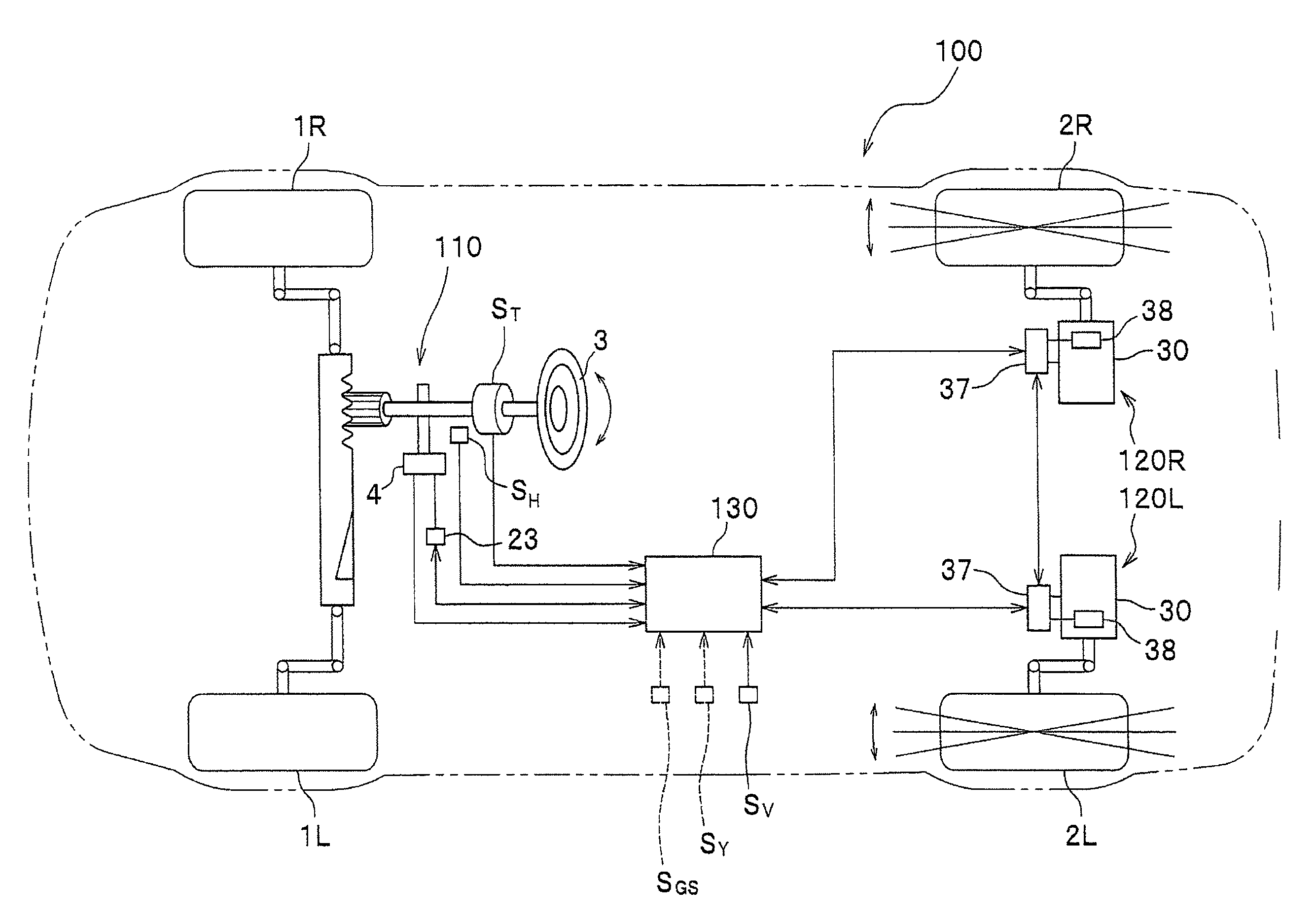
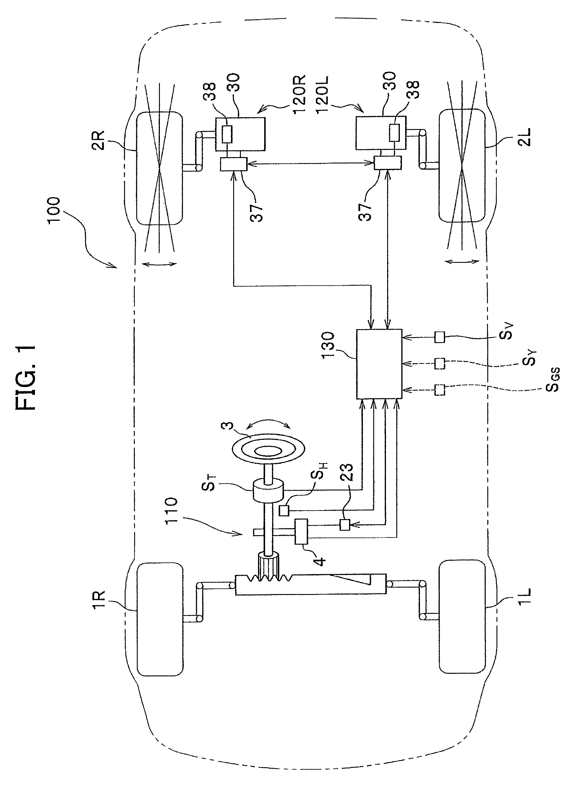
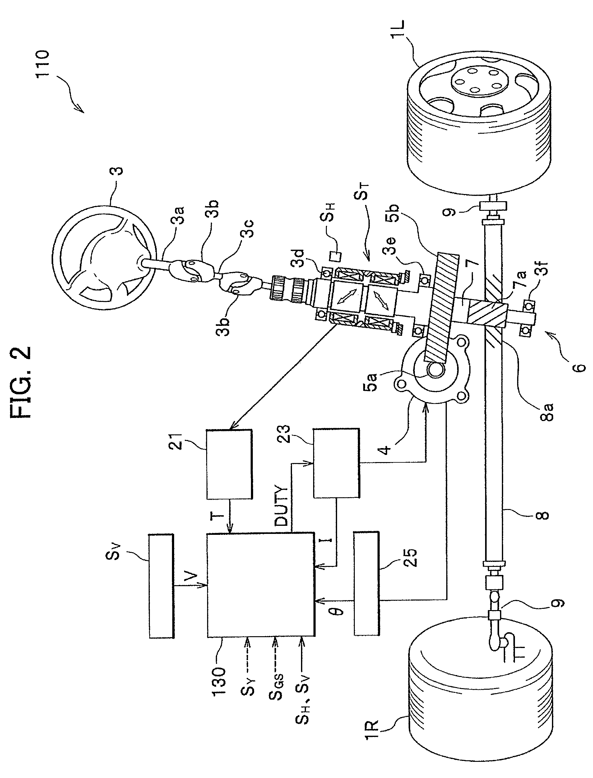
[0018]Hereinafter, a best mode for carrying out the invention (hereinafter, an “embodiment”) will be explained. In the explanation, the attached drawings will be referred to. In addition, FIG. 1 is a schematic diagram of an entire four-wheel vehicle having a toe angle changer according to an embodiment of the present invention. FIG. 2 is a diagram of an electric power steering device.

[0019]As shown in FIG. 1, a steering system 100 includes an electric power steering device 110 having an electric motor 4, which is configured to assist steering of left and right front wheels 1L, 1R by a steering wheel 3, and toe angle changers 120L, 120R configured to independently change toe angles of rear wheels 2L, 2R by respective actuators 30, in accordance with a steering angle of the steering wheel 3 and a vehicle speed. The steering system 100 further includes a steering controller 130 (hereinafter, referred to as “steering control ECU (Electronic Control Unit)”) configured to control the elec...


PUM


Abstract

The present invention improves response characteristics in turning traveling of a vehicle while traveling stability at the time of turning is kept. The present invention provides a system in which toe angles of left and right rear wheels are controlled based on a steering angular velocity, not a steering angle of a steering. In a steering system in which toe angles of left and right rear wheels are controlled independently, a steering angular velocity is calculated from a steering angle, and toe angle changers are controlled to tilt the toe angle of the right rear wheel to the left when the steering angular velocity is on the left side, and is controlled to tilt the toe angle of the left rear wheel to the left when the steering angular velocity is on the right side.

Description

CROSS REFERENCE TO RELATED APPLICATIONS[0001]The present application claims benefit of the filing date of Japanese Patent Application No. 2007-312376 filed on Dec. 3, 2007 which is incorporated herein by reference.FIELD OF THE INVENTION[0002]The present invention relates to a steering system for controlling toe angles of left and right rear wheels of a four-wheeled vehicle independently.DESCRIPTION OF THE RELATED ART[0003]In the prior art, in order to improve turning characteristics, a variety of four-wheel steering apparatuses for controlling toe angles of rear wheels have been proposed. For example, in JP 06-047388 B (1994), the fact that the toe angles of left and right rear wheels are controlled independently based on a steering angle of a steering wheel and a vehicle speed.[0004]However, as described in JP 06-047388 B (1994), controlling the toe angles of the left and right rear wheels based on the steering angle of the steering wheel (setting aside the vehicle speed) causes de...

Claims


Application Information

Patent Timeline
Patent Type & Authority Patents(United States)
IPC IPC(8): B62D5/06
CPCB62D7/146B62D17/00
Inventor SASAKI, HIROAKIHORIUCHI, YUTAKAYANAGI, TAKASHI
Owner HONDA MOTOR CO LTD
Learn More