Method and apparatus for inhibiting pitch formation in the wet seal exhaust duct of a veneer dryer

a dryer and wet seal technology, applied in the direction of drying machines with progressive movements, lighting and heating apparatus, furnaces, etc., can solve the problems of insufficient maintenance and cleaning practices, insufficient exhaust control settings, pitch build-up is a fire hazard, etc., and achieve the effect of reducing outflow and increasing exhaust flow

Active Publication Date: 2011-11-01
USNRKOCKUMS CANCAR +1
View PDF8 Cites 9 Cited by
  • Summary
  • Abstract
  • Description
  • Claims
  • Application Information

AI Technical Summary

Benefits of technology

[0006]The present invention provides a new and improved apparatus and method for controlling a dryer. In the illustrated embodiment, the invention is applied to a jet veneer dryer used to reduce the moisture content of rigid and semi-rigid sheet material, such as green veneer, wet plasterboard, fiberboard, perlite and the like, and to heat the input seal chamber exhaust gases above the pitch (V.O.C.) condensation temperatures.
[0010]A flow controller controls an inlet damper communicating with the main exhaust fan. The damper is operative to reduce or increase the rate of exhaust flow through the main exhaust system as a function of the sensed temperature difference.
[0012]The input seal chamber includes restricted passages formed in stop-off members located at the entry point to the input seal chamber. These restricted passages allow a controlled amount of ambient air to enter the input chamber. The sampling fan draws sufficient gases from the input seal chamber to reduce the pressure within the input seal chamber to a level only slightly below atmospheric. As a result, ambient air enters the input seal section and is in effect mixed with exhaust gases which bleed from the drying chamber into the input seal chamber. The rate of exhaust bleed into the seal chamber (which is a function of the pressure build-up within the drying chamber), affects the temperature of gases drawn from the wet end seal section by the sampling fan. An increase in temperature of the sampled gases indicates that excess exhaust gas is being produced in the drying chamber. According to one aspect of the invention, a controller operatively connected to a sampled gas temperature sensor and an ambient temperature sensor adjusts the damper of the main exhaust system to increase the exhaust flow. Conversely, as the temperature of the sampled gas decrease, the controller will reduce the outflow of exhaust gas through the main exhaust system.
[0014]A reheat subsystem may be provided in order to maintain the temperature of the gases exhausted by the first drying or preheat section, above a predetermined minimum. The present invention contemplates the treatment of exhaust gases by a catalytic, thermal oxidizer or other V.O.C. eliminating devices. To optimize performance of this type of treatment apparatus, the temperature of exhaust gas can be maintained above a predetermined level. According to this embodiment of the invention, the first drying section includes a means for receiving heated gas from a remote drying section. In particular, this embodiment includes at least three serially connected drying sections. The first drying section includes a downblast blower which is connected via a conduit to the plenum of a remote drying section which is preferably the third drying section as counted from the input end of the drying chamber. A temperature sensor monitors the flow of exhaust gases into the main exhaust system from the first drying section. Should the temperature fall below a predetermined minimum, gases from the third drying section which are at a higher temperature than the gases in the first drying section, are added to the first drying section to increase the overall temperature of gases exhausted from the first drying section by the main exhaust system.
[0020]According to a further embodiment of the present invention there is disclosed a method for operating a dryer. The method comprises the steps of providing a drying chamber having a plurality of individual drying sections, cross-communicating fan inlet plenums of the drying sections and provides a single point exhaust system communicating with a first drying section. The method further comprises controlling a rate of exhaust flow out of the first drying section by monitoring a temperature of ambient air drawn into a wet seal section and comparing it with a temperature of gases sampled from the wet seal section, adjusting the rate of exhaust flow in the single point exhaust system in order to maintain a substantially constant temperature differential between the ambient air temperature and the temperature of gases sampled from the wet seal section and heating the gases sampled from the wet seal section above a pitch condensation temperature of pitch contained in the gases sampled.

Problems solved by technology

However, pitch build-up, condensed V.O.C. material, in the exhaust fan duct of the wet end seal resulted from the lower exhaust stream temperature inherent to that design, which may also have been contributed to by improper setting of the exhaust control by dryer operators and insufficient maintenance and cleaning practices.
Obviously, pitch build-up represents a fire hazard.
A fire in the exhaust fan duct would result in costly repairs and downtime.

Method used


Image

  • Method and apparatus for inhibiting pitch formation in the wet seal exhaust duct of a veneer dryer
  • Method and apparatus for inhibiting pitch formation in the wet seal exhaust duct of a veneer dryer
  • Method and apparatus for inhibiting pitch formation in the wet seal exhaust duct of a veneer dryer

Examples


Embodiment Construction

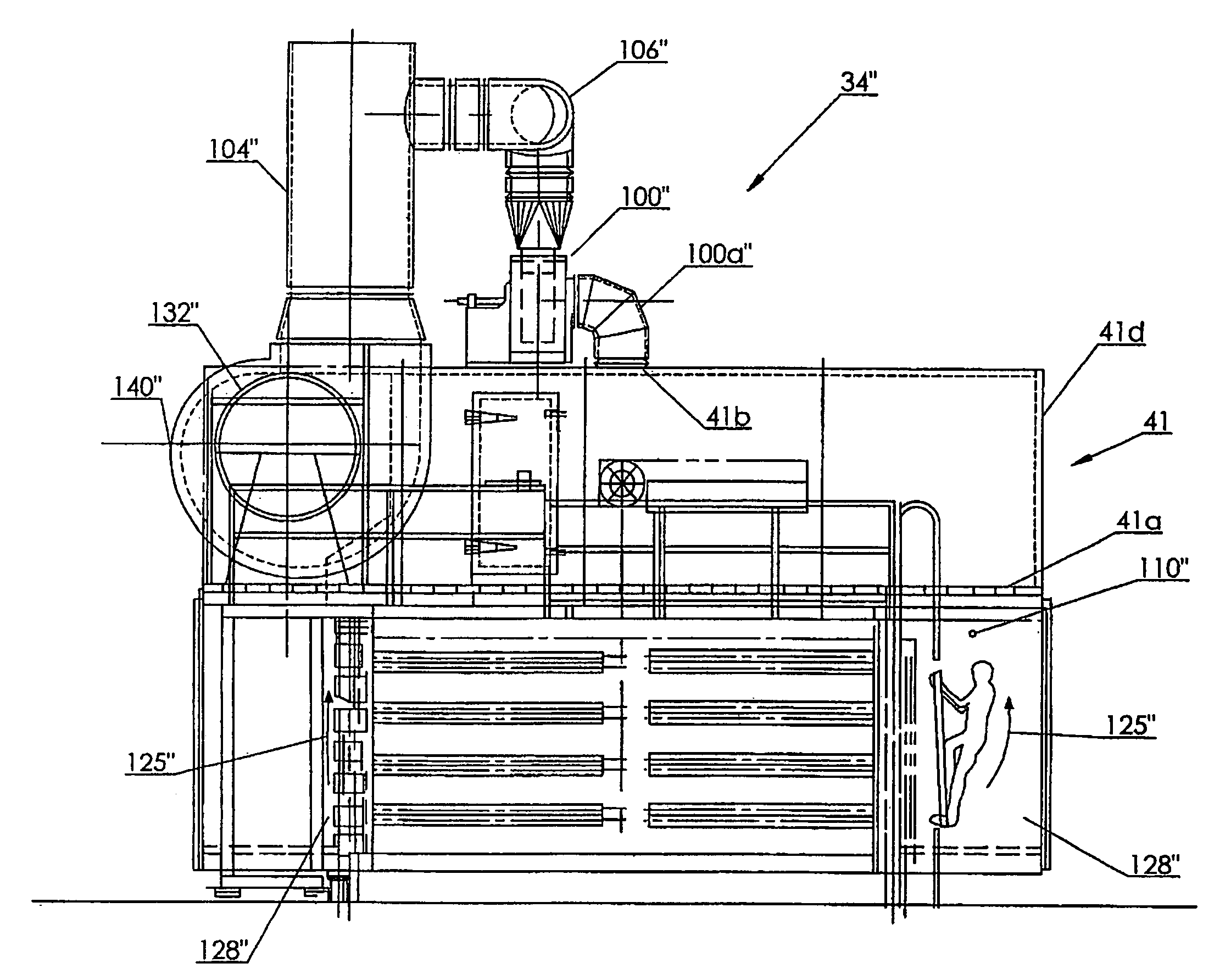
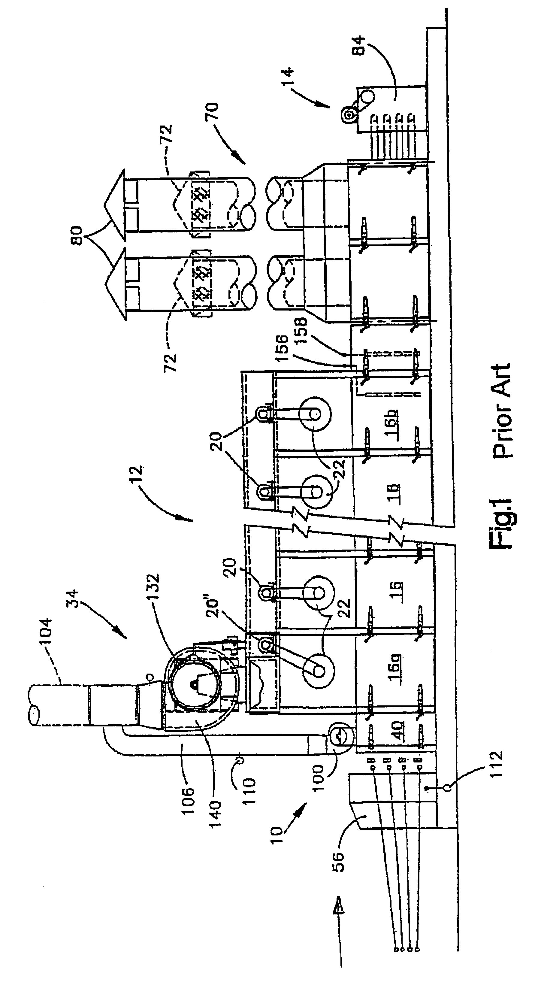
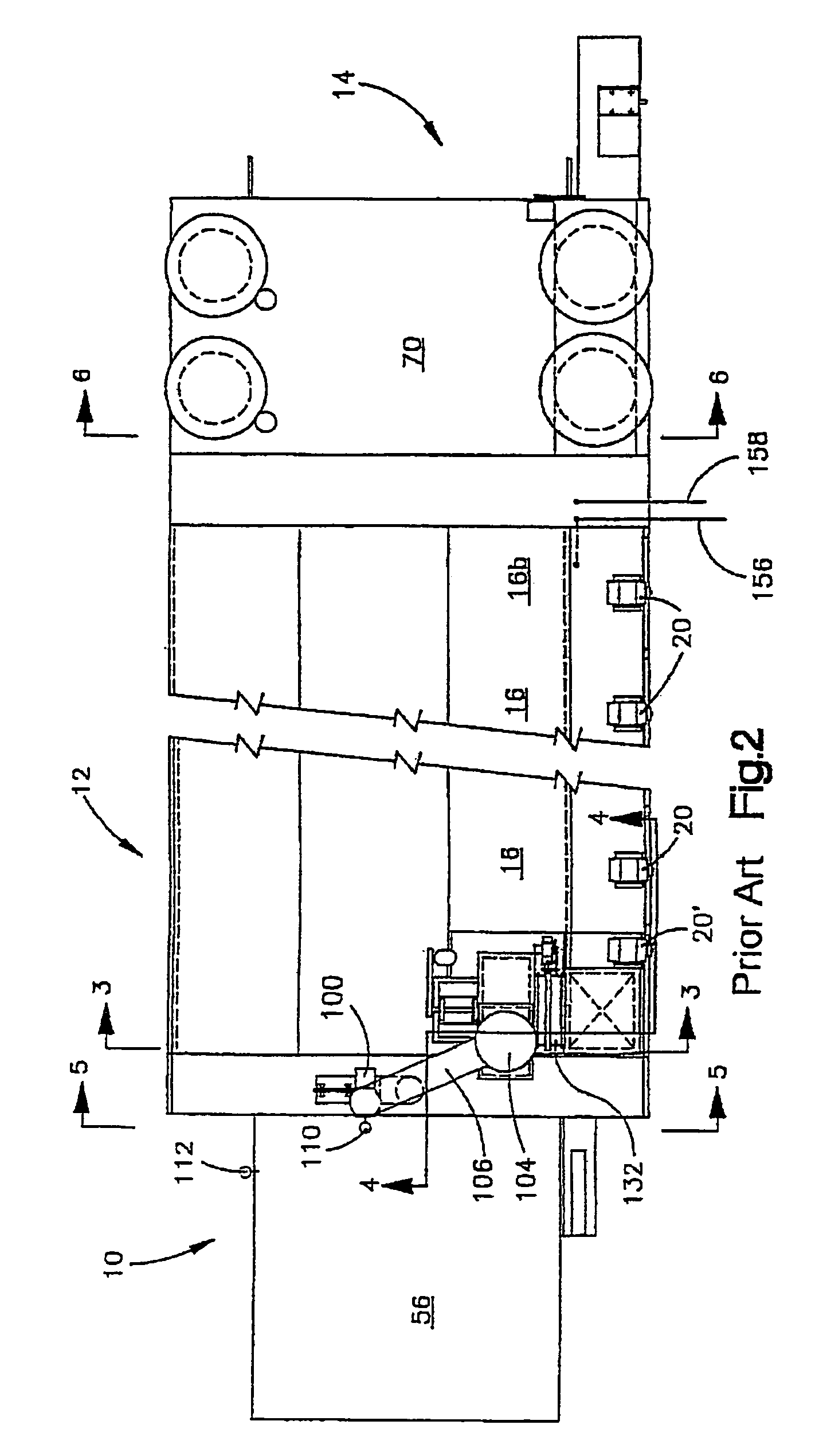
[0037]As disclosed in U.S. Pat. No. 5,603,168, FIGS. 1 and 2 illustrate the overall construction of a jet veneer dryer. A “jet veneer dryer” is the type of dryer which is used to reduce the moisture content of, or dry, sheet material, such as wood veneers, pulp board, plasterboard, fiberboard, perlite board, and the like. The material to be dried is introduced at a “wet end”10 of the apparatus, is conveyed through a drying chamber 12, ultimately exiting the apparatus at a “dry end”14.

[0038]The illustrated prior art dryer includes a plurality of juxtaposed, drying sections 16 which, in the illustrated embodiment, are virtually identical. Each drying section 16 is considered conventional and includes a drive motor 20 for driving an axial-type fan 22 which circulates air within the drying section in a circular path, transverse to the path of movement of material through the drying chamber 12.

[0039]As moisture is driven from the material passing through the chamber 12, the volume of gas...


PUM


Abstract

A method and apparatus for operating a dryer used to reduce the moisture content of sheet material. A drying chamber is provided and includes a plurality of drying sections and a single point exhaust system. A seal section located at the input end of the dryer includes an exhaust passage through which a gas sample is drawn by a sampling fan. Gases within the seal section are a combination of ambient air drawn through restricted passages at the entry to the seal section and exhaust gas that bleeds into the seal section from the drying chamber. A controller monitors the temperature of the sampled gases and ambient air and adjusts the rate of exhaust flow from the main exhaust system as a function of the temperature differential. A heating system is also provided for heating the seal exhaust gases above the pitch condensation temperature for the flow.

Description

CROSS REFERENCE TO RELATED APPLICATION[0001]This application claims priority from U.S. Provisional Patent Application No. 60 / 851,050 filed Oct. 12, 2006 entitled Method and Apparatus for Inhibiting Pitch Formation in the Exhaust Ducts of a Veneer Dryer.FIELD OF THE INVENTION[0002]The present invention relates generally to apparatus and methods for drying material and, in particular, to an apparatus and method for controlling the type of dryer used to reduce the moisture content of material such as wood veneers, plasterboard, etc.BACKGROUND OF THE INVENTION[0003]Single and multiple deck conveyor dryers for reducing the moisture content of various materials, including rigid and semi-rigid material in sheet form, such as, green veneer, wet plasterboard, fiberboard, perlite and bagasse matte and the like, wherein the material being dried is conveyed through a stationary housing on one or a plurality of tiered conveyors while heated gases are force circulated through the housing or a par...

Claims


Application Information

Patent Timeline
Patent Type & Authority Patents(United States)
IPC IPC(8): F26B3/00
CPCF26B13/10F26B21/02F26B23/02F26B25/008F26B3/02F26B2210/14
Inventor WOLOWIECKI, BRYAN
Owner USNRKOCKUMS CANCAR
Why Eureka
Try Eureka