
Surveying method, surveying system and surveying data processing program

a surveying system and data processing technology, applied in the field of surveying methods, surveying systems, and surveying data processing programs, can solve the problems of data-lacking portion, inability to obtain reflected light, and inability to obtain data, so as to facilitate the acquisition of point cloud data and obtain data.

Active Publication Date: 2011-10-25
KK TOPCON
View PDF11 Cites 63 Cited by
  • Summary
  • Abstract
  • Description
  • Claims
  • Application Information

AI Technical Summary

Benefits of technology

Enables the efficient and accurate acquisition of complete point cloud data without data gaps, reducing the time and effort required for data collection by visually identifying and filling in missing data areas using image matching and stereoscopic image processing.

Problems solved by technology

However, when obstacle(s) such as a vehicle, a tree, etc. are present in the measurement area, shadow (occlusion) occurs, and this causes a portion where the data is lacking.
Also, because a distance is measured by the reflection of a pulsed laser beam, if reflectivity at the projecting point is low, e.g. if the laser beam used is in green color when the reflection point is in black color or in complementary color (i.e. in red color), the reflected light cannot be obtained.
This causes a data-lacking portion to occur, too.
Further, when the measurement area is scanned from a horizontal direction, point cloud data cannot be obtained on the upper surface of a building or a structure, for instance.
This means that tremendous efforts and long time are required for the surveying operation.
Also, when reflectivity is low at the point to be measured, such inconveniences often arise that the point cloud data cannot be obtained.

Method used


Image

  • Surveying method, surveying system and surveying data processing program
  • Surveying method, surveying system and surveying data processing program
  • Surveying method, surveying system and surveying data processing program

Examples


Embodiment Construction

[0054]Referring to the attached drawings, detailed description will be given below on the best mode when the present invention is carried out.

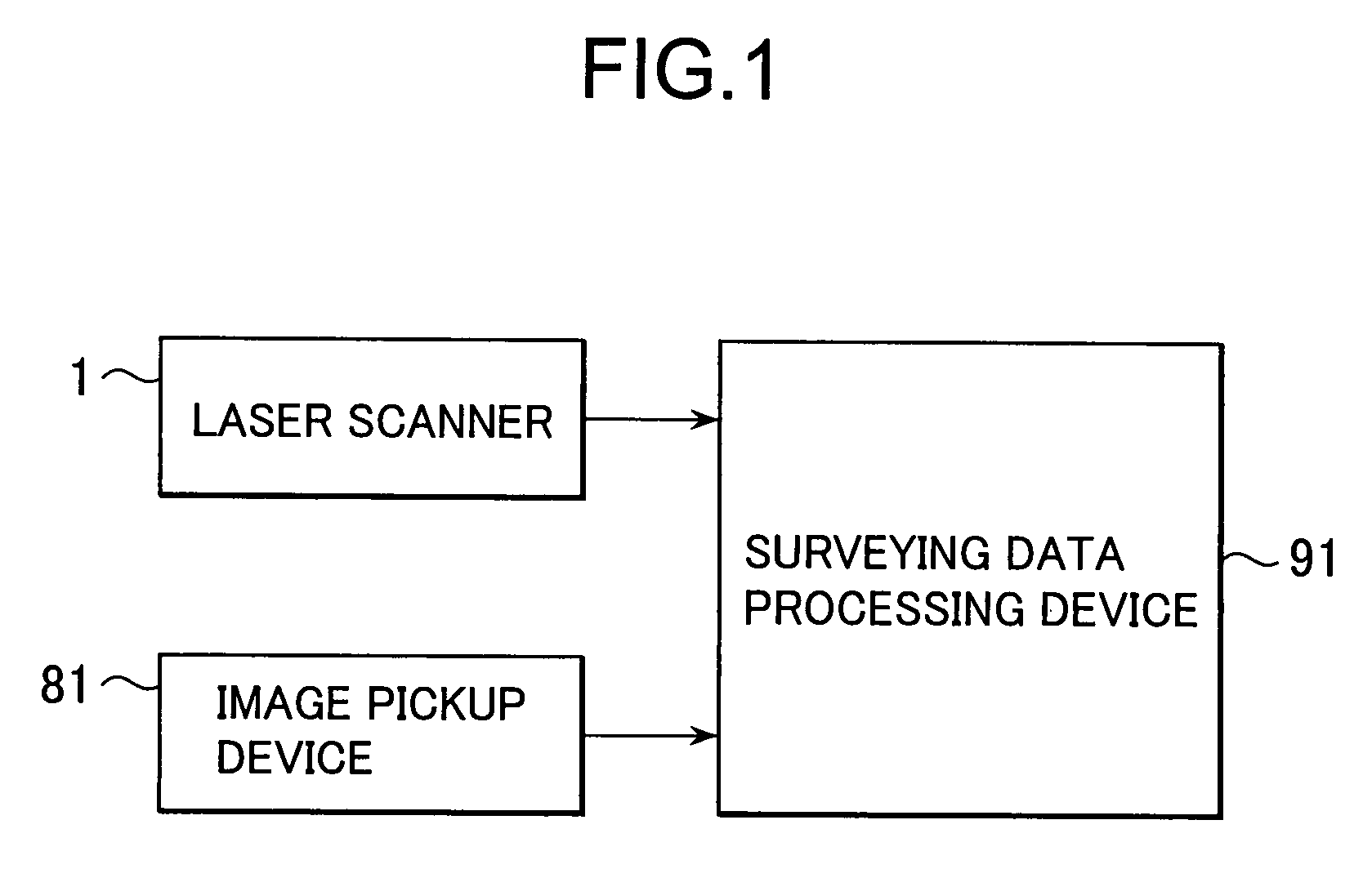
[0055]Referring to FIG. 1, description will be given below on a laser scanner used in the present invention.

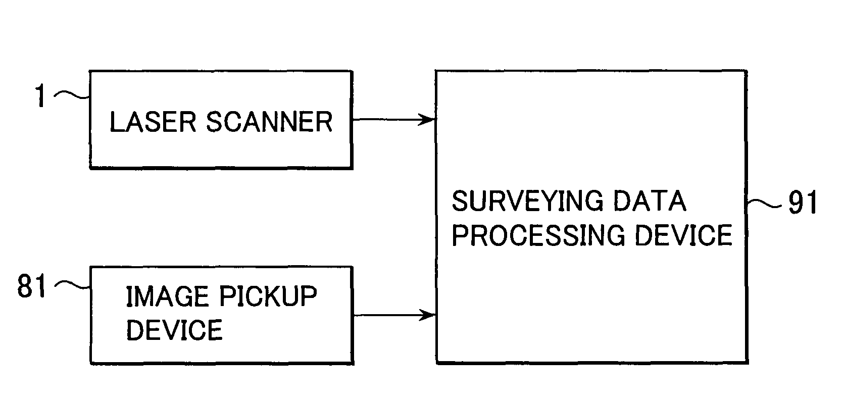
[0056]As shown in FIG. 1, a surveying system according to the present invention generally comprises a laser scanner 1, an image pickup device 81 typically represented by a digital camera or the like, and a surveying data processing device 91.

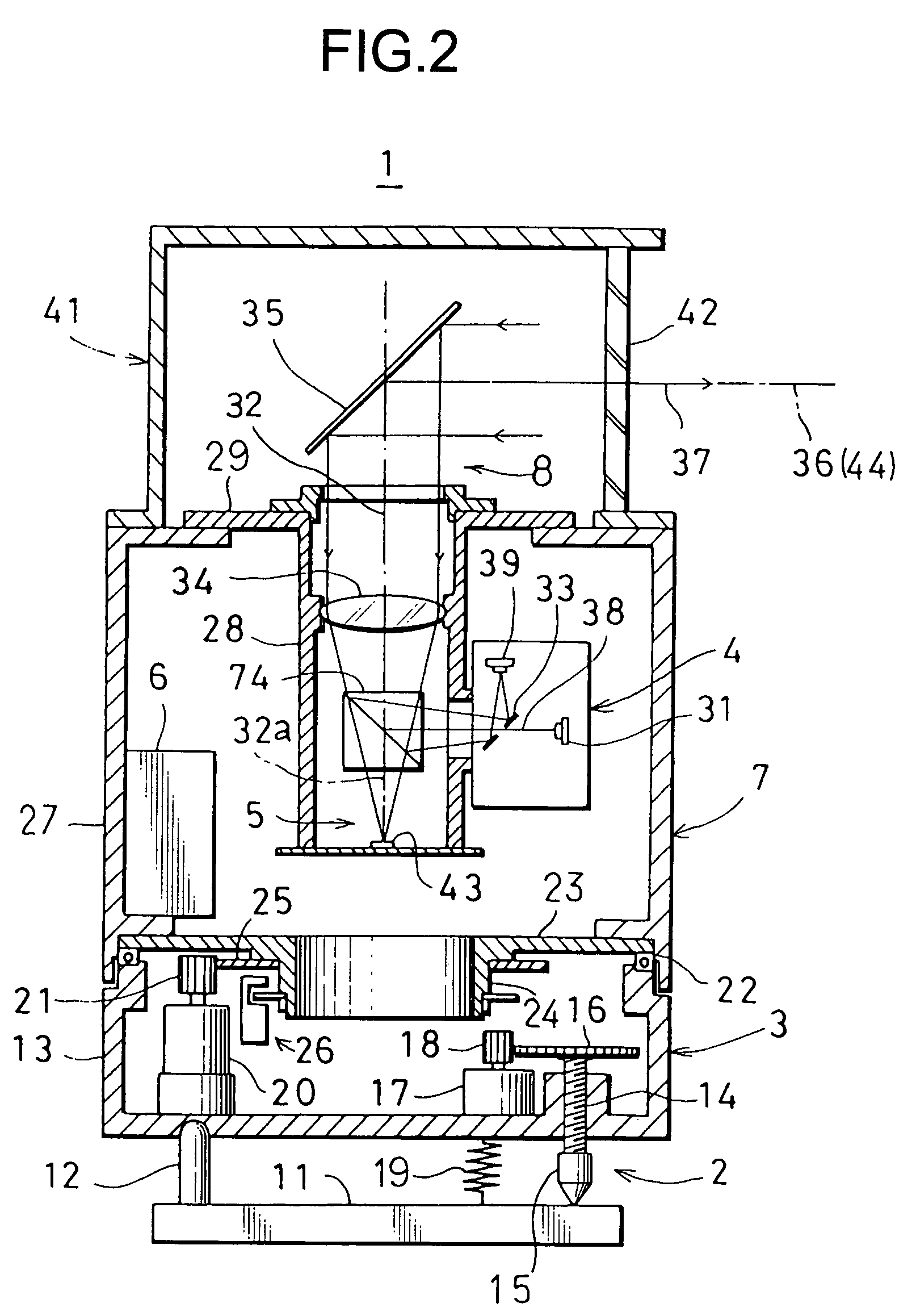
[0057]First, referring to FIG. 2 to FIG. 17, description will be given on the laser scanner used in the invention.

[0058]FIG. 2 and FIG. 3 each represents a first example of the laser scanner.

[0059]The laser scanner 1 primarily comprises a leveling unit 2, a rotary mechanism 3 installed on the leveling unit 2, a measuring system main unit 7 supported by the rotary mechanism 3 and including a distance measuring unit 4, an image pickup unit 5, a control unit 6, etc., and a rotary projecting unit 8 mount...


PUM


Abstract

There are provided a step of acquiring a main point cloud data on a predetermined measurement range by a laser scanner, a step of detecting a range with no data acquired, a step of acquiring a supplementary image data of the range with no data acquired by an auxiliary image pickup device, a step of preparing a stereoscopic image based on the supplementary image data obtained by the auxiliary image pickup device, a step of acquiring supplementary point cloud data from the stereoscopic image, and a step of supplementing the range with no data acquired of the main point cloud data by matching of the main point cloud data and the supplementary point cloud data.

Description

BACKGROUND OF THE INVENTION[0001]The present invention relates to a surveying method, a surveying system, and a surveying data processing program for acquiring three-dimensional data of a predetermined area.[0002]In recent years, three-dimensional surveying on three-dimensional object has been more frequently performed, and there are now growing demands on an image with three-dimensional data to be used for an electronic map. Because of such circumstances or the like, the amount of the data required for surveying purpose has extensively increased.[0003]A laser scanner is known as a surveying system for measuring a large amount of three-dimensional data in detail and within short time.[0004]A laser scanner is a surveying system for projecting a pulsed laser beam to a predetermined measurement area, for receiving a reflected light of the pulsed laser beam to measure three-dimensional position data at a projecting point of the pulsed laser beam for each pulse, and for acquiring point c...

Claims


Application Information

Patent Timeline
Patent Type & Authority Patents(United States)
IPC IPC(8): G06K9/00H04N7/16H04N15/00G01S17/86G01S17/89
CPCG01C3/00G01C11/025G01C11/06G01S7/4817G01S17/023G01S17/89G06T7/0057G06T7/0065G01S17/42G06T2207/10012G06T2207/10028G06T2207/30184G06T7/521G06T7/55G01S17/86
Inventor OTANI, HITOSHIITO, TADAYUKI
Owner KK TOPCON
Learn More