Control apparatus for AC motor
a control apparatus and motor technology, applied in the direction of motor/generator/converter stopper, dynamo-electric gear control, dynamo-electric converter control, etc., can solve the problems of cumbersome data input, generate the need for interpolation between non-continuous data, etc., to achieve high response, more accurately and more simply and conveniently set, and high torque control
- Summary
- Abstract
- Description
- Claims
- Application Information
AI Technical Summary
Benefits of technology
Problems solved by technology
Method used
Image
Examples
embodiment 1
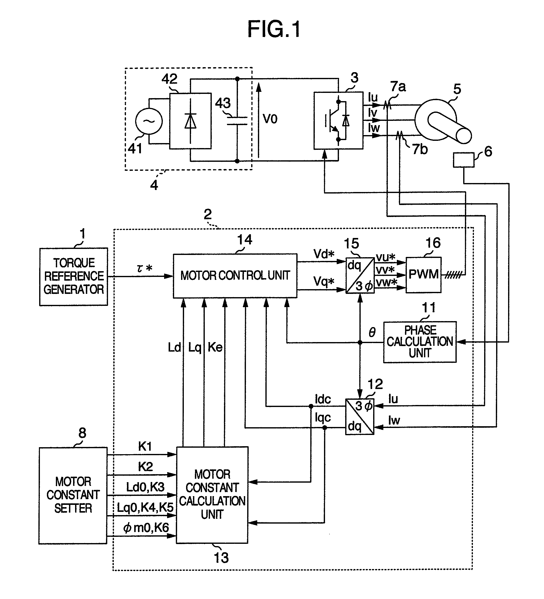
FIG. 1 is a block diagram showing a system configuration of embodiment 1 of a control apparatus of an AC motor according to the present invention. A control apparatus of the present embodiment 1 is configured by a torque reference generator 1 for giving torque reference τ* to a motor, a controller 2 for calculating AC applied voltage of a motor and for outputting it by converting to a pulse width modulated signal (hereafter abbreviated as a PWM signal), an inverter 3 driven by this PWM signal, a DC power source 4 for supplying power to the inverter 3, a permanent magnet type synchronous motor 5 (hereafter abbreviated as a PM motor) as a controlled object, a position detector 6 for detecting position of a rotor of the PM motor 5, an electric current detector 7a for detecting electric current Iu supplied to the PM motor by the inverter 3, an electric current detector 7b for detecting electric current Iw, and a motor constant setter 8 for setting constants K1, K2, K3, K4, K5, K6, Ld0, ...
embodiment 2
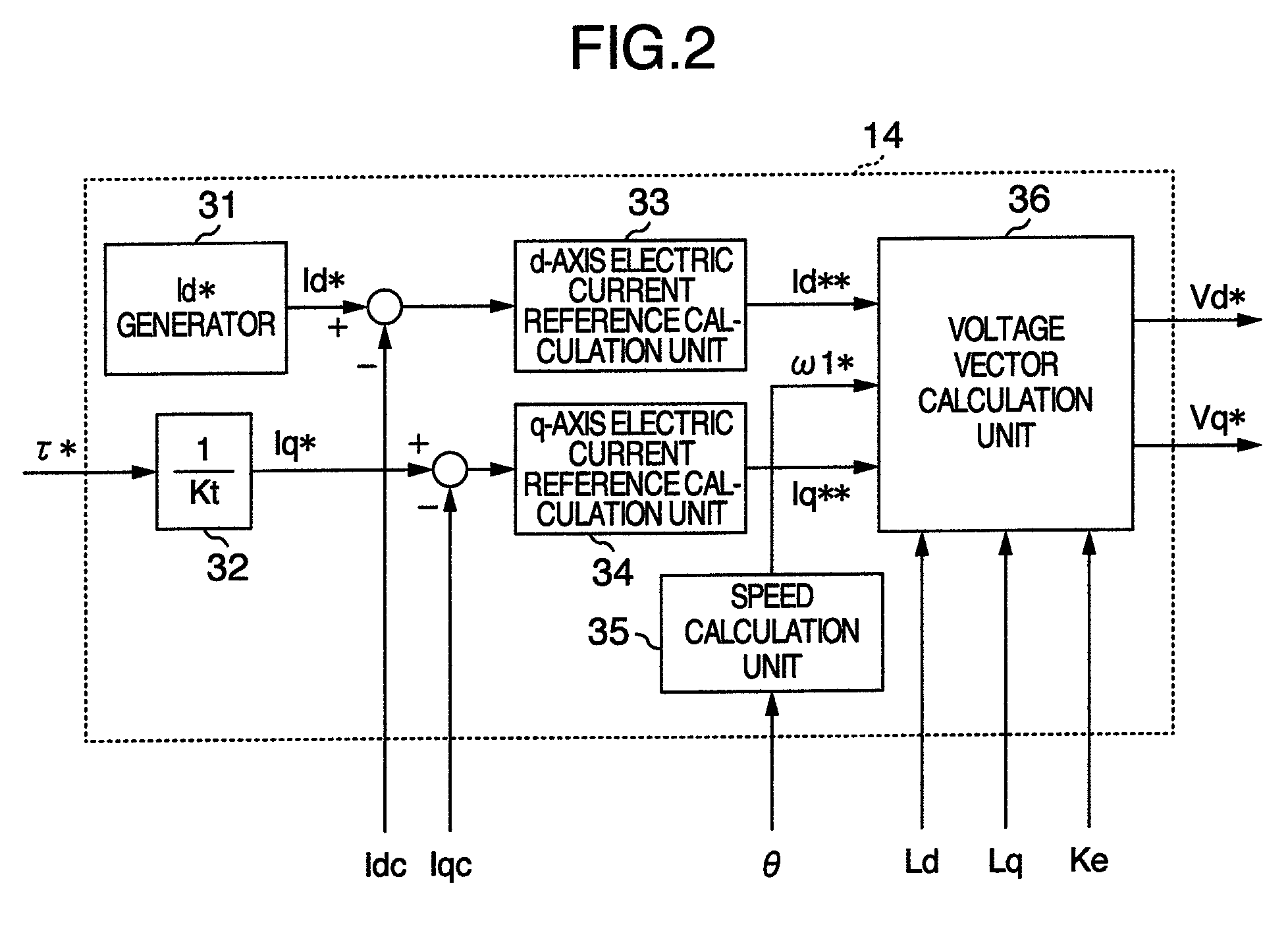
In embodiment 2, the motor control unit 14 is substituted with a motor control unit 14a shown in FIG. 8. Different points of FIG. 8 from FIG. 2 are absence of conversion coefficient 32, and calculation of a torque estimation value τc by being provided with a torque calculation unit 37.
The electric constants Ld, Lq and Ke of the PM motor, which are output by the motor constant calculation unit 13, and detected currents Idc and Iqc are input to the torque calculation unit 37, and the torque estimation value τc is calculated by the following function expression.
τc=Ke×Iqc+(Ld−Lq)×Idc×Iqc (Equation 15)
By using electric constants Ld, Lq and Ke of the PM motor, which are output by the motor constant calculation unit 13, in torque estimation calculation, as described above, which is features of the present invention, highly precise torque control and high response can be attained, even when electric constants of a motor vary with increase in motor electric current caused by high load or th...
embodiment 3
In embodiment 1 and embodiment 2, explanations were given on configuration of the case having both a position sensor and an electric current sensor, however, configuration of the case having a position sensorless and an electric current sensor is also attainable. Explanation will be given with reference to FIG. 9.
Different points of FIG. 9 from FIG. 1 are as follows. Firstly, the torque reference generator 1 is substituted with a speed reference generator 1a, the motor control unit 14 is substituted with a motor control unit 14b, and still more the position detector 6 and the phase calculation unit 11 are eliminated, and phase angle θdc is supplied from the motor control unit 14b.
As for a setting method for the electric constants, a method explained in embodiment 1 is used.
Next, explanation will be given in detail on actuation of the motor control unit 14b with reference to FIG. 10.
Configuration of the motor control unit 14b shown in the present embodiment is nearly the same as tha...
PUM
 Abstract
Description
Claims
Application Information
 - R&D
- Intellectual Property
- Life Sciences
- Materials
- Tech Scout
- Unparalleled Data Quality
- Higher Quality Content
- 60% Fewer Hallucinations
Browse by: Latest US Patents, China's latest patents, Technical Efficacy Thesaurus, Application Domain, Technology Topic, Popular Technical Reports.
© 2025 PatSnap. All rights reserved.Legal|Privacy policy|Modern Slavery Act Transparency Statement|Sitemap|About US| Contact US: help@patsnap.com


