
Multi-Modal Active RFID Tag With Biometric Sensors, Systems and Methods of ITV Tracking

a multi-modal, active technology, applied in the field of active multi-modal radio frequency identification (rfid) tags and systems, can solve the problems of severe limitations dictated by physics, non-operational, and limited range of passive tags and readers, and achieve the effect of effective direction

Active Publication Date: 2008-03-13
INNOVATION LAW GROUP
View PDF13 Cites 93 Cited by
  • Summary
  • Abstract
  • Description
  • Claims
  • Application Information

AI Technical Summary

Benefits of technology

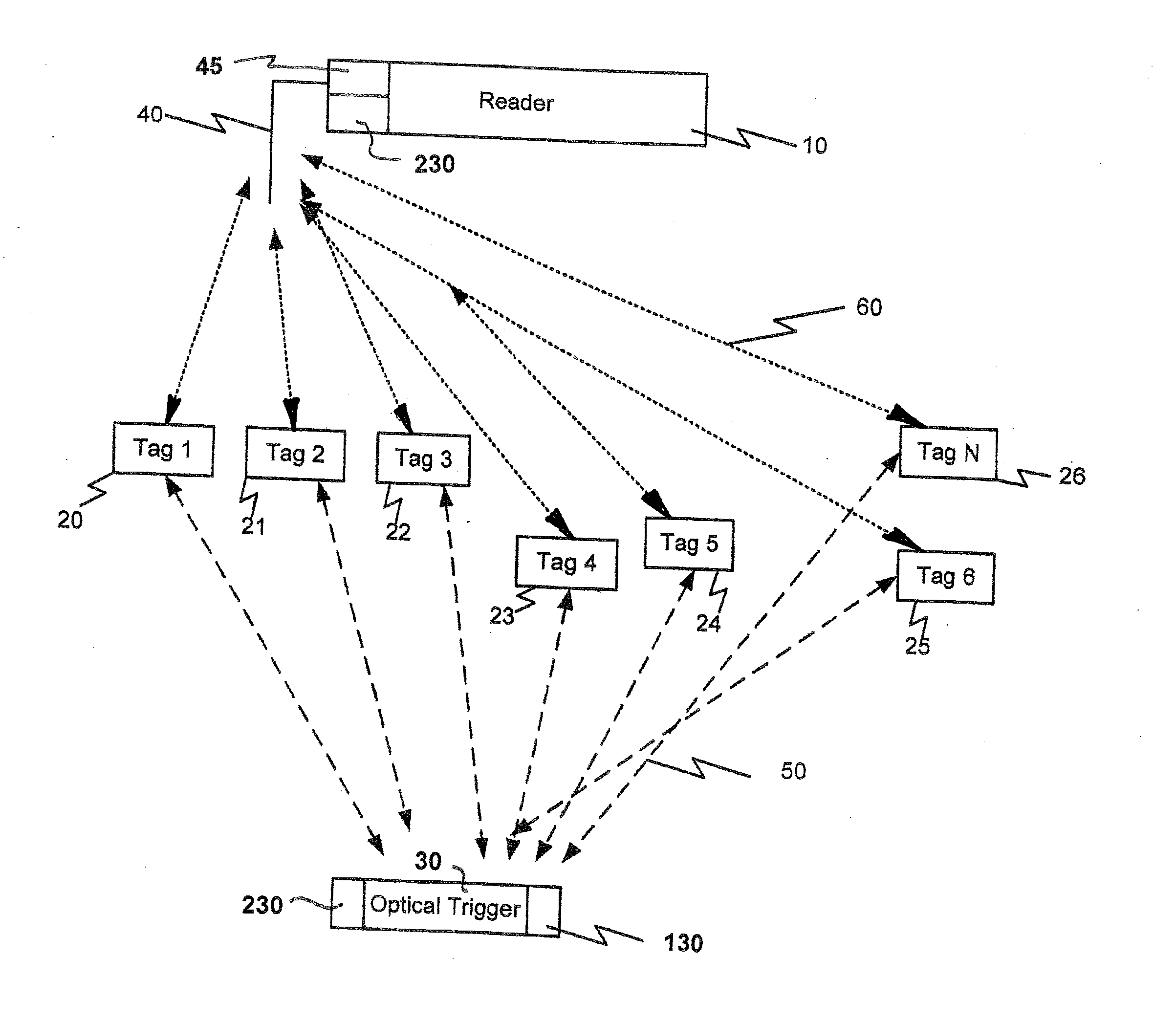
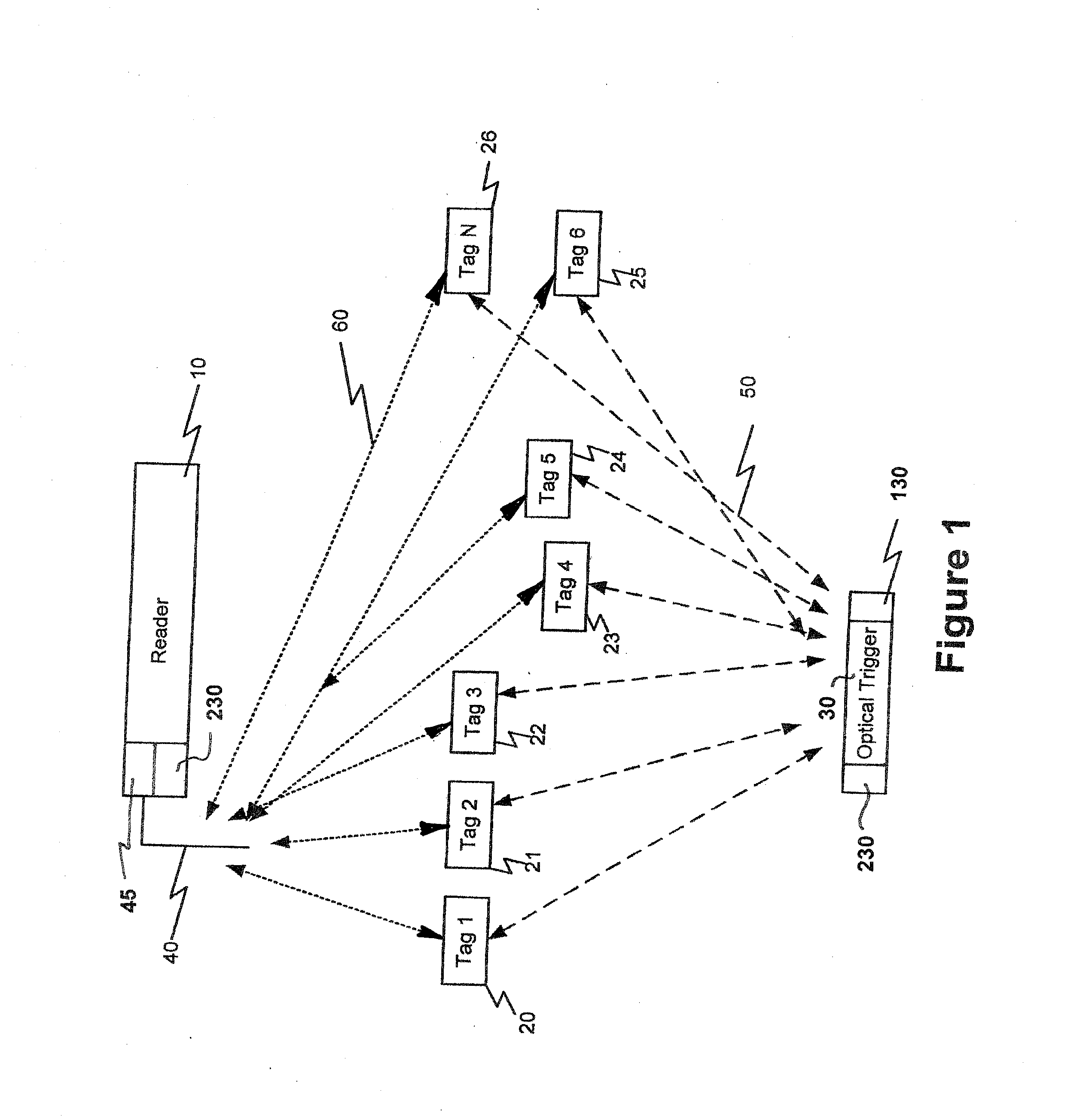
[0011] This combination of dual-mode or multi-mode communications allows long range and autonomous tracking of objects to be realized through the RF transmit mode, while providing local communication (transfer) of data simultaneously through the secondary mode of communication. The ability to communicate through optical or ultrasonic secondary mode means that radio silence can be maintained (such as when on aircraft), while the total tag functionality of data transfer can be accomplished through the secondary mode. It also means that a tag can be triggered to transmit the RF signal on a discriminatory basis.
[0039] In regard to the tracking and guest inventory aspects described above as applications of the inventive system, large cruise ships may debark in excess of 2000 passengers at an interim stop, and the time ashore may be only on the order of a few hours. In addition, ships often must sail within defined periods, when the tides permit. Keeping track of which guests leave and whether any are left behind is time consuming, reducing time ashore, and difficult, at best. Accordingly, issuing wrist bands or lanyard tags permits automatic “inventory” of guests going ashore and returning, as their tags are triggered by an illuminator as they pass through a portal to leave the ship, and logged back in when they return. That gives an instant ID of who may be left behind. With a WAN system in place, on-shore establishments may also be in the network, so that positive location of the missing few is possible. In addition, the use of the LED time period notification or / and guidance system may be enabled for this class of users. This system is also useful for airline stop-overs, employee tracking, patients in hospitals, including new-borns, elderly, Alzheimer patients, and the like.

Problems solved by technology

While passive tags and readers are relatively inexpensive, they have severe limitations dictated by physics.
For example, passive tags and readers have a limited range (from 0.1 cm to 6 meters) and are non-operational when blocked or shielded by metal objects, liquids and certain solid materials.
In such systems, data rates are limited such that a moving object having a tag affixed to it which needs to be read may not travel in excess of approximately 6 mph “drive-thru” speeds thru portals, conveyors, etc, that is, no more than a brisk walk.
Further, passive systems have limited data storage capacity and no sensing capability.
A disadvantage of active tags is that they cost more than passive tags and this requires that these tags must achieve maximum performance, add value to supply chain management, have useful battery life and permit easy replacement or recharging of batteries, while achieving these goals at absolute lowest cost.
However, this approach has limitations.
In many instances, the continuous battery consumption is prohibitive, since RF data transfer is really only required at change of events, that is, for example, when handling or processing the tagged items.
In addition, it is often desired to associate a specific tagged item with a process such that the tagged item can be associated with a specific event, time or operator and beacon tags do not provide this utility.
RF and magnetic triggered tags have the problem of being non-discriminatory.
That is, “singulation”, single tag actuation from amongst many, is not possible, by which is meant that picking one item out of many by trying to communicate with that object's tag by RF is not practicable.
This is due to the nature of RF fields; they cannot be restrained to a narrow effective Field of View (FOV) and hence are not tag-specific in the presence of many tags.
They are also costly.
Low frequencies (of the electro-magnetic domain) such as 125-134 KHz require very close proximity to actuate the tag response and often will not work at all, well or consistently, where the tag is attached to ferrous objects.
Higher frequencies are often reflected, creating a background of RF noise that makes single tag actuation less reliable than is required.
Similarly, IR noise such as generated by light, TV appliances (particularly LCD and plasma TVs), and heat sources significantly affect IR tags.
All of these triggering mechanisms are large, bulky, and expensive.
Handheld triggers or communicators are also large and bulky.
This task is significantly complicated and more costly with low frequency devices due to the necessity for relatively high source power.
Additionally, the transfer of data is at relatively low speeds.

Method used


Image

  • Multi-Modal Active RFID Tag With Biometric Sensors, Systems and Methods of ITV Tracking
  • Multi-Modal Active RFID Tag With Biometric Sensors, Systems and Methods of ITV Tracking
  • Multi-Modal Active RFID Tag With Biometric Sensors, Systems and Methods of ITV Tracking

Examples


Embodiment Construction

[0051] The following detailed description illustrates the invention by way of example, not by way of limitation of the scope, equivalents or principles of the invention. This description will clearly enable one skilled in the art to make and use the invention, and describes several embodiments, adaptations, variations, alternatives and uses of the invention, including what is presently believed to be the best modes of carrying out the invention.

[0052] In this regard, the invention is illustrated in the several figures, and is of sufficient complexity that the many parts, interrelationships, and sub-combinations thereof simply cannot be fully illustrated in a single patent-type drawing. For clarity and conciseness, several of the drawings show in schematic, or omit, parts that are not essential in that drawing to a description of a particular feature, aspect or principle of the invention being disclosed. Thus, the best mode embodiment of one feature may be shown in one drawing, and ...


PUM


Abstract

RFID tags, methods and systems for total asset management, in-transit visibility and bio-metric verification and authorization. The system comprises an active, multi-modal, bi-directional RFID tag having a primary communication mode RF transceiver and a secondary mode IR / US transceiver. The tag includes sensors, such as bio-metric, and memory containing user bio-metric data. A reader and illuminator(s), preferably IR and / or US, are communicatively coupled with the tag and adapted to provide command and control signals to the tag and receive data / information from it. The user's bio-metric data is read by the sensor, compared to the data base and verification communicated to an access or point of sale device. The tag looks for illuminators and reports to the reader the IDs of those it sees. The detection history permits tracking and locating tagged objects or persons, such as theme park guests. If no illuminator signal is seen, the tag sends a special signal.

Description

CROSS REFERENCE TO RELATED APPLICATIONS [0001] This application is a continuation in part of parent U.S. Ser. No. 11 / 082,237, filed Mar. 17, 2005 by the same inventor, titled “Active RFID Tag Utilizing a Secondary Communication Mode”, now U.S. Pat. No. 7,295,108, Issued Nov. 13, 2007, which in turn is based on priority Provisional Application 60 / 555,153, filed Mar. 22, 2004 by the same inventor under the same title, the benefits of the filing dates of which are claimed under 35 US Code §§119 and 120ff, and the disclosures of which are incorporated herein by reference.FIELD OF THE INVENTION [0002] The invention relates to the field of active multi-modal Radio Frequency Identification (RFID) tags and systems, and more particularly to bi-modal and tri-modal tags, systems of illuminators, readers and tags, and methods of In Transit Visibility (ITV) and Total Asset Management (TAM), including use of biometric sensors on or as part of the system in association with the tags More particula...

Claims


Application Information

Patent Timeline
IPC IPC(8): G08B13/14G06K19/06G06K19/07G06K19/073H04Q5/22
CPCG06K7/10079G06K19/0723G06K19/145G06K19/07345G06K19/0728
Inventor CORRADO, ANTHONY P.
Owner INNOVATION LAW GROUP
Learn More