
Wireless telemetry electronic circuit board for high temperature environments

a technology of electronic circuit board and high temperature environment, which is applied in the direction of printed circuit structure association, printed circuit assembling, fixed capacitors, etc., can solve the problems of high cost, low efficiency, and low efficiency of current state of the art circuits using silicon or silicon-on-insulator active components that cannot operate at such high temperatures

Inactive Publication Date: 2011-09-20
CREE FAYETTEVILLE +1
View PDF96 Cites 19 Cited by
  • Summary
  • Abstract
  • Description
  • Claims
  • Application Information

AI Technical Summary

Benefits of technology

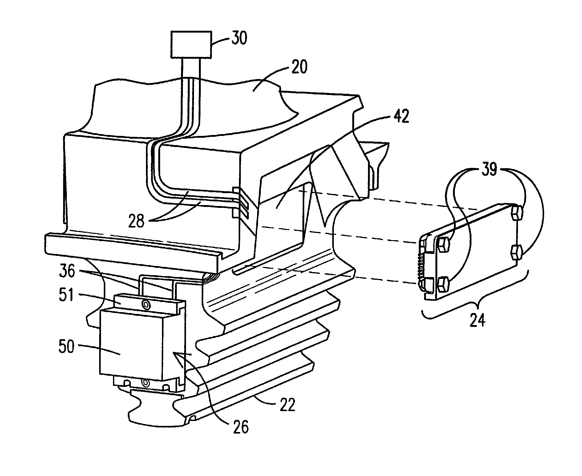
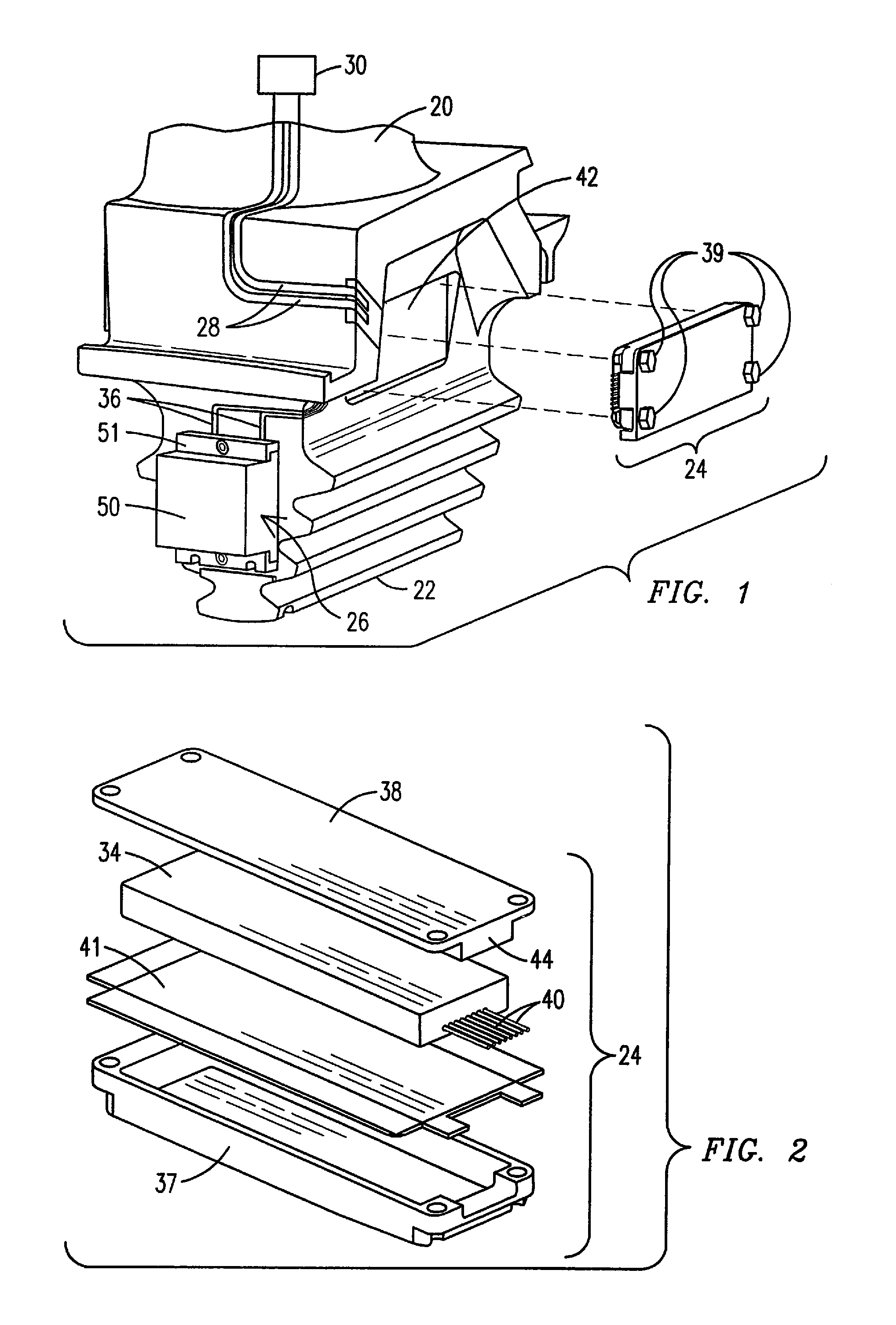
"The present invention is about a wireless telemetry circuit board that can withstand high temperatures in excess of 300°C and can withstand high forces up to at least 1000 g's. This circuit board can be used in high-temperature environments such as gas turbine engines, aircraft engines, and turbines used in the oil and gas industry. The invention solves the problem of slow, labor-intensive, expensive, and modified component mounting of traditional lead wired circuits in high-temperature environments. The wireless telemetry circuit board can provide real-time monitoring of component conditions during operation of turbine engines, optimize turbine operation, and enable condition-based maintenance. The invention is useful for reducing operation costs of advanced turbine engines and improving the efficiency of turbines."

Problems solved by technology

The process is slow, labor intensive, expensive, and requires modification of many of the components of the turbine in order to allow for the inclusion of all of the lead wires.
Current state of the art circuits using silicon or silicon-on-insulator (SOI) active components are not capable of operation at such high temperatures.

Method used


Image

  • Wireless telemetry electronic circuit board for high temperature environments
  • Wireless telemetry electronic circuit board for high temperature environments
  • Wireless telemetry electronic circuit board for high temperature environments

Examples


Embodiment Construction

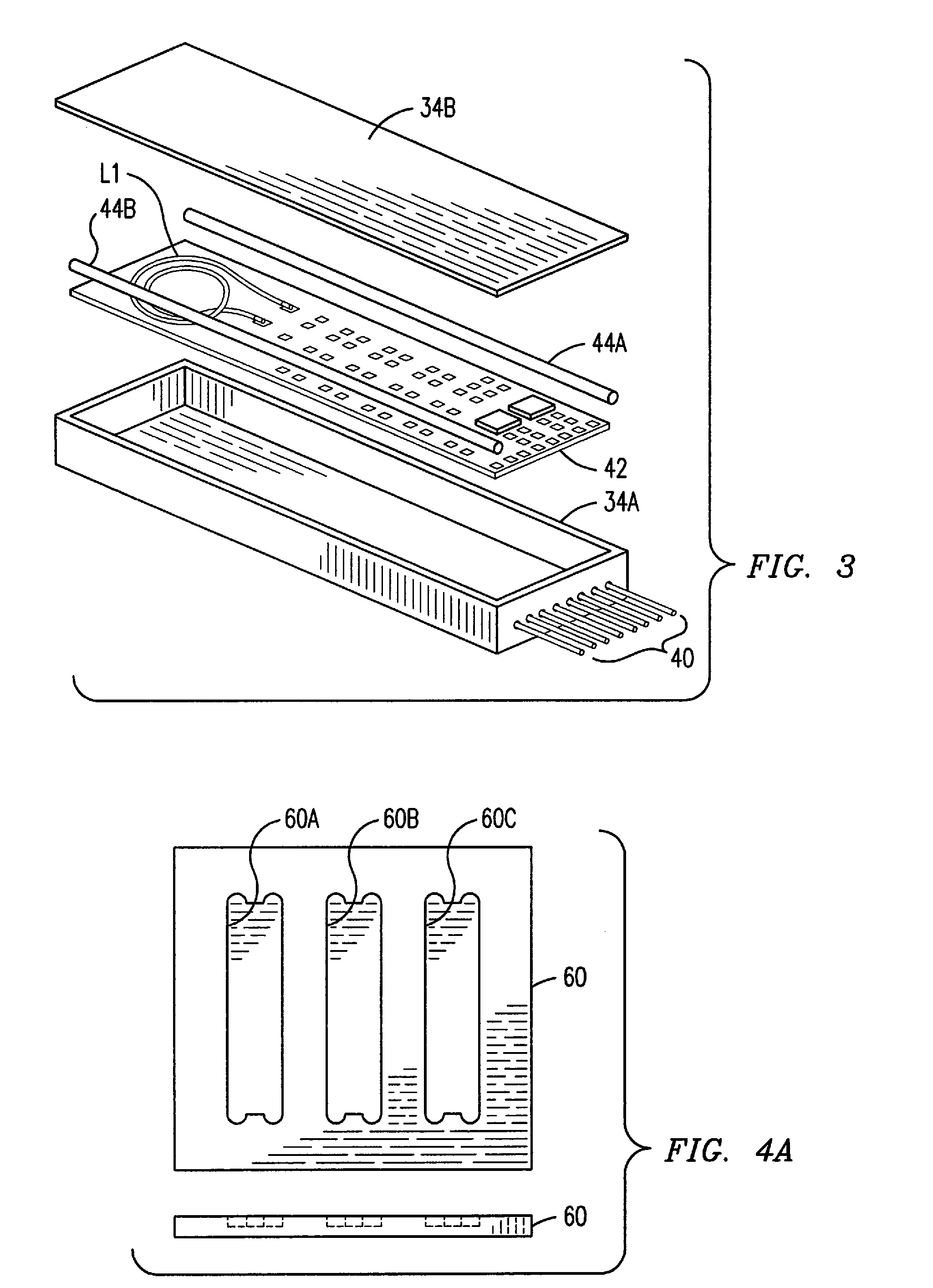
[0030]Embodiments disclosed herein enable transmission of data via wireless telemetry by the use of an electronic circuit from regions of a gas turbine with temperatures ranging from ambient to greater than 300° C., and including temperatures up to at least 450° C. All of the elements of the circuit and package therefore are to be fabricated from materials capable of operation at temperatures greater than 300° C. Current state of the art high temperature electronic systems are designed such that the control logic circuits are placed in a location cool enough to use silicon-based electronics, or high temperature silicon-on-insulator (HTSOI) technology capable of operation at elevated temperatures up to a maximum of 300° C. In such a current state of the art system, the control signals are sent from a region of relatively low temperature, via a wire, to a power amplification module that is located in the hot region, at temperatures greater than 300° C. The power amplification module i...


PUM

PropertyMeasurementUnit
temperatureaaaaaaaaaa
temperaturesaaaaaaaaaa

Abstract

A circuit assembly (34) resistant to high-temperature and high g centrifugal force is disclosed. A printed circuit board (42) is first fabricated from alumina and has conductive traces of said circuit formed thereon by the use of a thick film gold paste. Active and passive components of the circuit assembly are attached to the printed circuit board by means of gold powder diffused under high temperature. Gold wire is used for bonding between the circuit traces and the active components in order to complete the circuit assembly (34). Also, a method for manufacturing a circuit assembly resistant to elevated temperature is disclosed.

Description

STATEMENT REGARDING FEDERALLY SPONSORED DEVELOPMENT[0001]Development for this invention was supported in part by Contract No. 70NANB4H3042, awarded by the National Institute of Standards and Technology. Accordingly, the United States Government may have certain rights in this invention.FIELD OF THE INVENTION[0002]The present invention generally relates to a wireless telemetry electronic circuit board and in particular to a circuit board that is capable of operating in high temperature environments exceeding 300° C. and capable of withstanding forces up to at least 1000 g's.BACKGROUND OF THE INVENTION[0003]The temperatures inside an operating gas turbine engine are extremely high, often at levels in excess of 450° C. When it is desirable to monitor the inside temperatures of components of the turbine, such as a turbine blade, or to monitor stresses placed upon such components during operation, a special sensing, amplifying and transmitting circuit is required. An effective solution t...

Claims


Application Information

Patent Timeline
Patent Type & Authority Patents(United States)
IPC IPC(8): H05K1/14
CPCH05K1/092H05K3/321H05K3/328G01K13/02G01K1/024Y10T29/53174H05K3/1291H05K2201/10674H05K2203/0186H05K2203/049H05K2203/0557H05K2203/1126H05K2203/167H01L2224/45139H01L2224/45144H01L2224/48472H05K3/102Y10T29/49139Y10T29/49144Y10T29/49128Y10T428/2947H01L2924/13062G01K2013/024H01L2924/3011H01L2924/01322H01L2924/00H01L2224/05644H01L2224/45015H01L2224/48644G01K13/024H01L2924/00014H01L2924/20751H01L2924/20752
Inventor MITCHELL, DAVID J.KULKARNI, ANAND A.SUBRAMANIAN, RAMESHROESCH, EDWARD R.WAITS, RODSCHUPBACH, ROBERTOFRALEY, JOHN R.LOSTETTER, ALEXANDER B.MCPHERSON, BRICEWESTERN, BRYON
Owner CREE FAYETTEVILLE
Learn More