Motor drive apparatus
a technology of motor drive and motor stopper, which is applied in the direction of motor/generator/converter stopper, electronic commutator, dynamo-electric converter control, etc., can solve the problems of affecting the operation of the motor. , to achieve the effect of reducing the interruption period of each drive current, reducing noise, and stable position detection
- Summary
- Abstract
- Description
- Claims
- Application Information
AI Technical Summary
Benefits of technology
Problems solved by technology
Method used
Image
Examples
embodiments
A. Apparatus Configuration
A-1. Overall Configuration
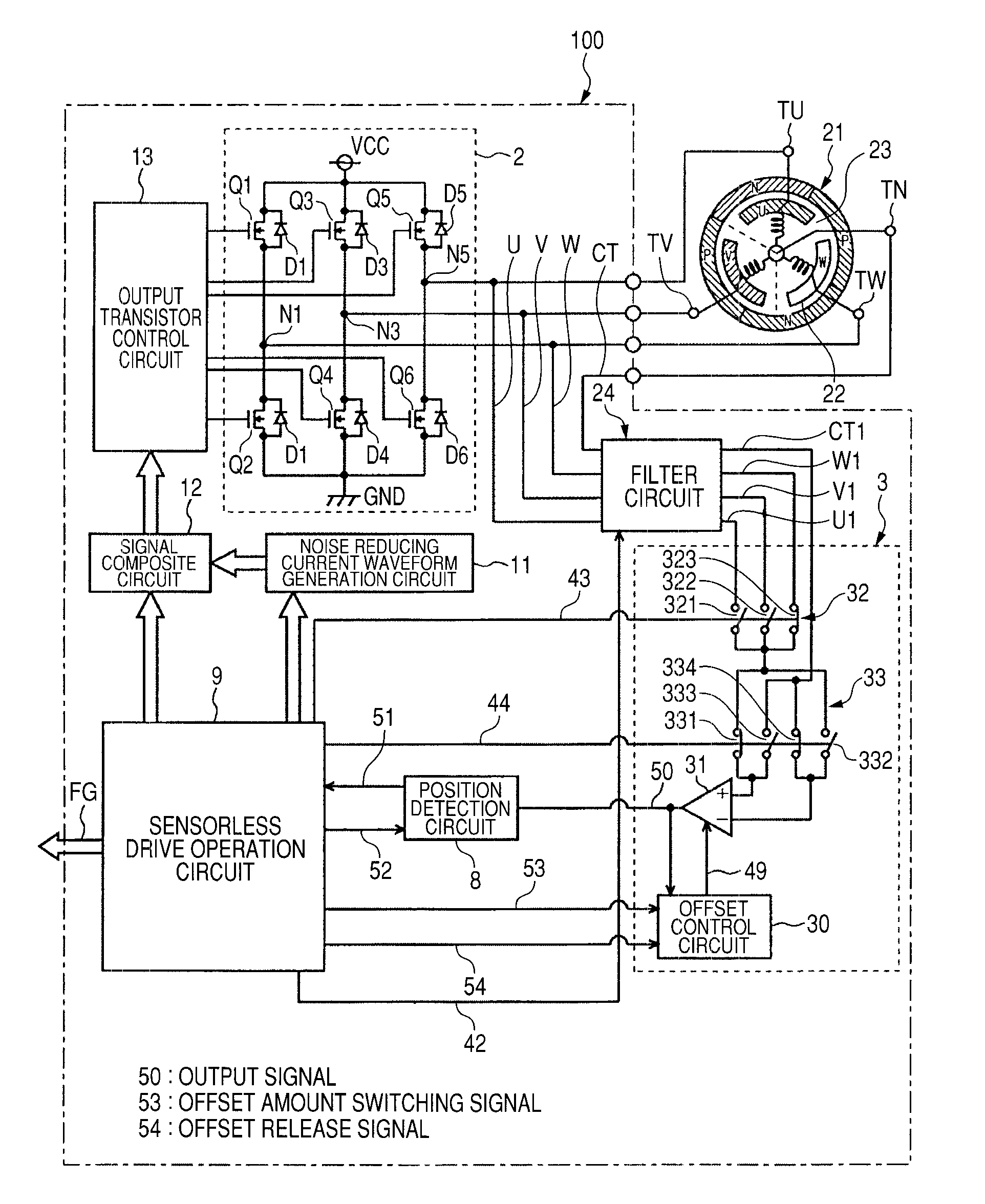
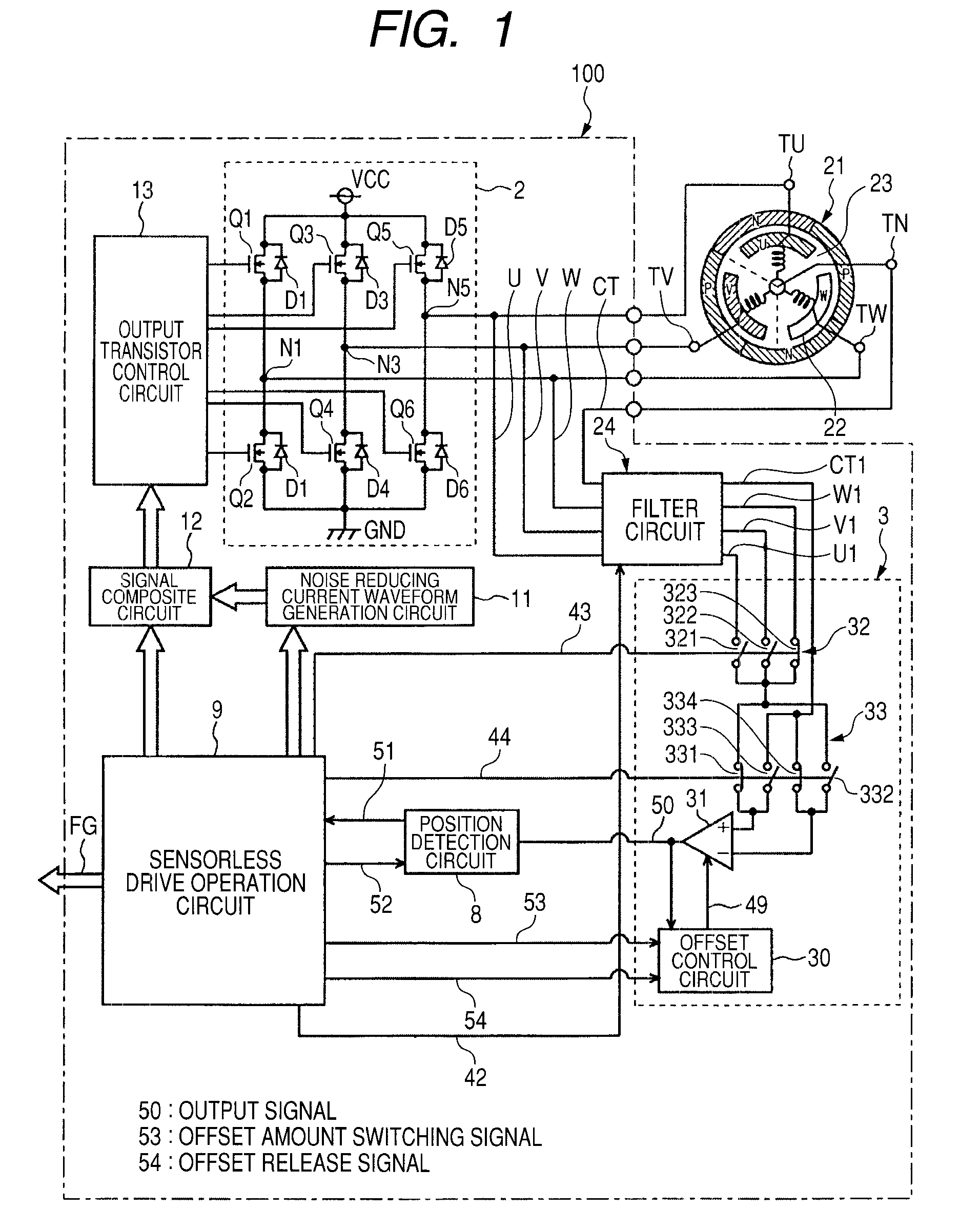
[0027]FIG. 1 is a block diagram showing a configuration of a motor drive apparatus 100 illustrative of an embodiment according to the present invention. As shown in FIG. 1, the motor drive apparatus 100 includes an output circuit 2, a filter circuit 24, a comparison circuit 3 (voltage comparison unit), a position detection circuit 8, a sensorless drive operation circuit 9 (drive operation unit), a noise reducing current waveform generation circuit 11, a signal composite circuit 12 and an output transistor control circuit 13. The motor drive apparatus 100 drives a 3-phase brushless motor 21 without using a Hall sensor. Incidentally, the motor drive apparatus 100 is formed as one IC (Integrated Circuit).
[0028]The 3-phase brushless motor 21 has a stator 22 and a rotor 23 rotatably provided therearound. The stator 22 includes Y-coupled coils of an U-phase, a V-phase and a W-phase. One ends of the coils of the U-phase, the V-phase and t...
first modification
D. First Modification
[0153]Although the motor drive apparatus 100 has such a configuration that as described using FIGS. 1 and 4, the comparison circuit 3 has the comparator 31 and the offset control circuit 30, and the offset control circuit 30 changes the offset control current 49 in the form of two stages thereby to make it possible to set the two offset values, the motor drive apparatus may be set to such a configuration that it has offset control circuits 30A and 30B different in offset value and two comparators 31 respectively controlled by the offset control circuits 30A and 30B as in a comparison circuit 3α shown in FIG. 13. Incidentally, the same reference numerals are respectively attached to the same components as those of the comparison circuit 3 described in FIGS. 1 and 4, and their dual explanations are omitted.
[0154]In this case, the comparator 31 controlled by the offset control circuit 30A is set to an offset value for detecting a point a by an offset control curren...
second modification
E. Second Modification
[0157]The motor drive apparatus 100 has such a configuration that as described using FIGS. 1 and 4, the comparison circuit 3 has one comparator 31 and one offset control circuit 30 and includes the signal switching unit 32 and the polarity switching unit 33 to supply the B-EMF voltages of the respective phases to the comparator 31 individually. However, as in a comparison circuit 3β shown in FIG. 14, such a configuration that comparators 31a, 31b and 31c respectively inputted with B-EMF voltages U1, V1 and W1 are provided, and the comparators 31a through 31c are controlled from an offset control circuit 30B, may be adopted. Incidentally, the same reference numerals are respectively attached to the same components as those of the comparison circuit 3 described in FIGS. 1 and 4, and their dual explanations are omitted.
[0158]In this case, the offset control circuit 30B has such a configuration as to switch control to the comparators 31a, 31b and 31c at timings pro...
PUM
 Abstract
Description
Claims
Application Information
 - R&D
- Intellectual Property
- Life Sciences
- Materials
- Tech Scout
- Unparalleled Data Quality
- Higher Quality Content
- 60% Fewer Hallucinations
Browse by: Latest US Patents, China's latest patents, Technical Efficacy Thesaurus, Application Domain, Technology Topic, Popular Technical Reports.
© 2025 PatSnap. All rights reserved.Legal|Privacy policy|Modern Slavery Act Transparency Statement|Sitemap|About US| Contact US: help@patsnap.com


