
Hearing instrument, and a method of operating a hearing instrument

a technology of hearing aids and hearing instruments, applied in the field of hearing aids, can solve the problems of affecting the design degree of freedom of vents, affecting the sound produced by hearing instruments, and unsatisfactory effects

Inactive Publication Date: 2011-09-06
SONOVA AG
View PDF12 Cites 2 Cited by
  • Summary
  • Abstract
  • Description
  • Claims
  • Application Information

AI Technical Summary

Benefits of technology

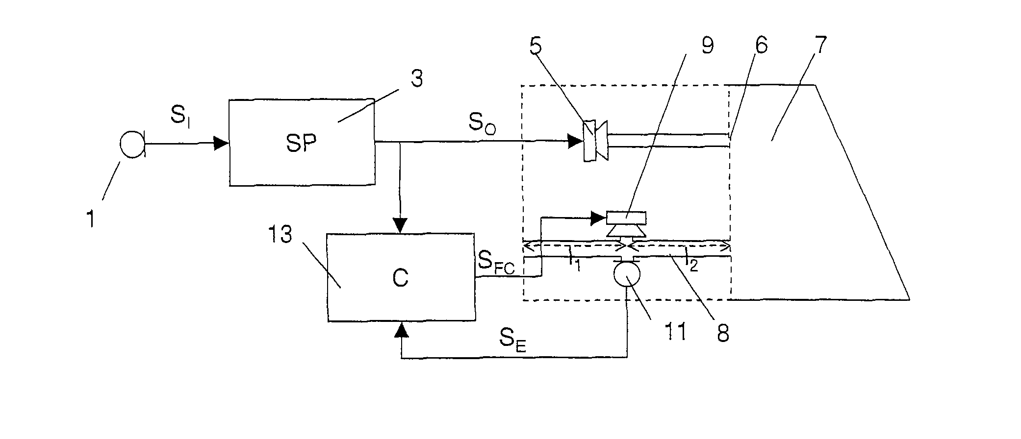
[0023]The acoustic compensation signal at least partially compensates by an active noise control process (also known as noise cancellation, or active noise reduction (ANR)) the signal in the duct and thus of the signal transmitted through the duct to the outside. In this way, the tendency for feedback is reduced. An additional effect may—depending on the chosen implementation—be that the direct sound that goes through the vent in the forward direction is also reduced, so that the wanted signal in the ear canal is easier to control.
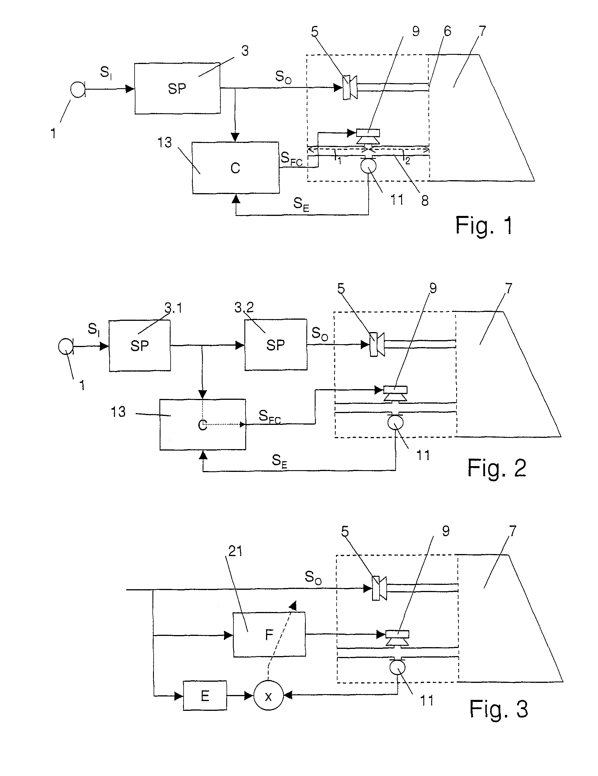
[0038]A compensation controller has at least two inputs: the first input from the signal path itself, processed in a real time, feed-forward manner into the compensation signal, and the auxiliary input from the error microphone by which the effect of the acoustic compensation signal may be surveyed and if necessary processing parameters may be adjusted. The processing of the duct acoustic signals into the processing parameters and / or processing structure can be done with a frequency corresponding to the sampling frequency or being of the same order of magnitude as the sampling frequency. It can as an alternative be done with a lower time-constant than the processing of the signal into the compensation signal. Then, the frequency with which the processing parameters are updated is comparably low, for example lower than the sampling rate of the acoustic input signal by an order of magnitude or more. This allows the error signal recorded by the error microphone (or a quantity dependent on it) to be integrated before processing, or the processing parameters to be (lowpass) filtered and / or integrated before being applied.
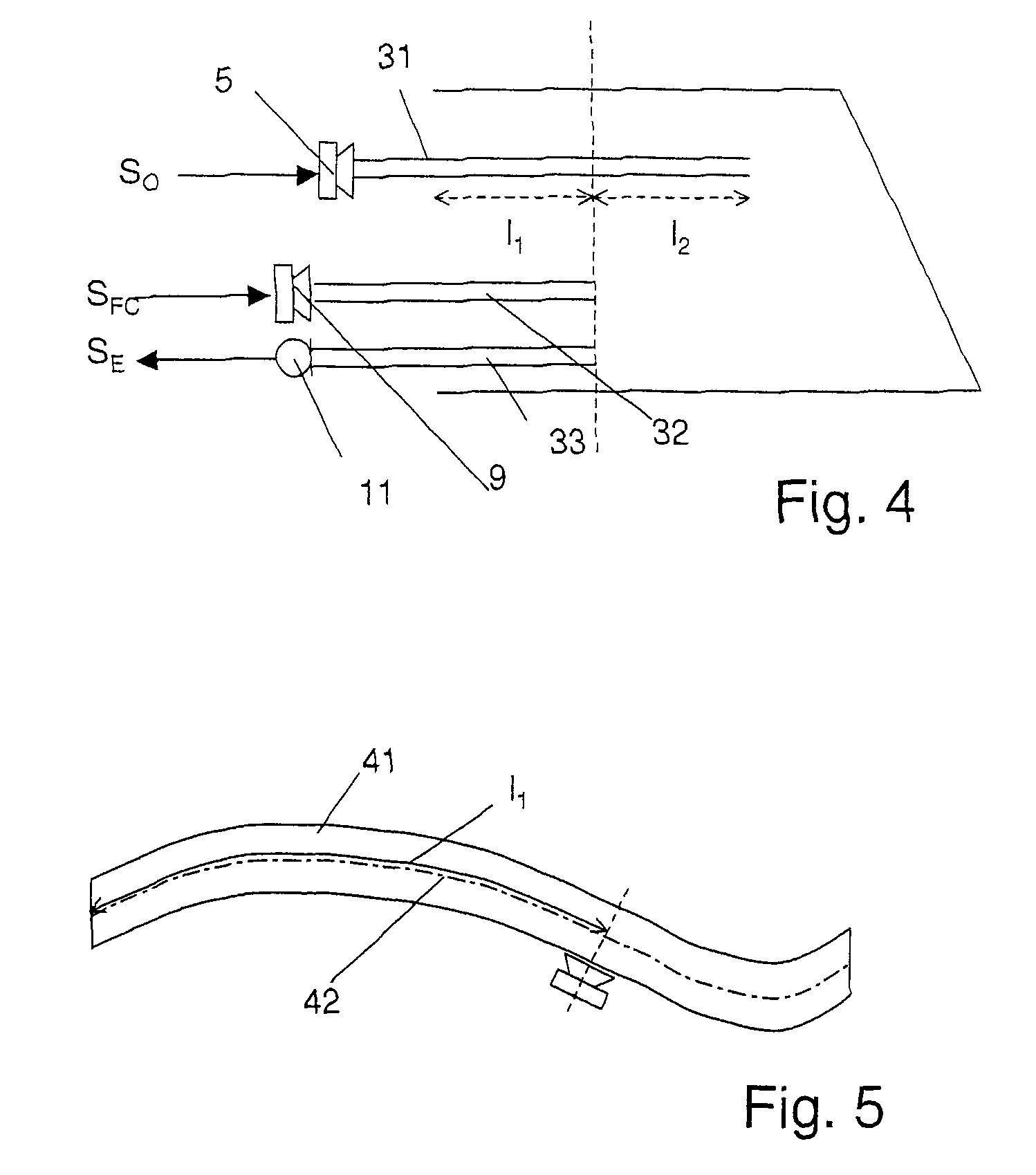
[0039]Due to the fact that the compensation signal is obtained from the signal path and not from the second microphone, and that the second microphone serves as an error microphone, it is not necessary that the second microphone is arranged upstream of the compensation receiver. The error signal may, in accordance with a preferred embodiment of the invention, be recorded in the same longitudinal position in which the acoustic compensation signal is radiated. This means that the compensation receiver and the error microphone are arranged at essentially the same position along the duct, i.e. the path of an acoustic signal from the compensation receiver intersects the duct at the same depth in the ear canal as the acoustic signal path to the error microphone. The possibility of arranging the compensation receiver and the error microphone at the same longitudinal position along the duct constitutes an important distinction from the prior art, where a microphone along the duct has to be place upstream of the compensation receiver. If the error microphone is at the same longitudinal position as the compensation receiver, the error signal recorded by the error microphone is a very good indicator of the efficiency with which the signal in the duct is cancelled by the compensation receiver.

Problems solved by technology

However, in these devices the space in the ear canal has to be used efficiently, and the ear canal essentially has to be closed by the device so as to minimize acoustic feedback due to the proximity of the sound outlet of the receiver and the sound inlet of the microphone.
This plugging of the ear canal may cause undesirable effects, known as occlusion effect which has an impact on the perception of the wearer's own voice and on the wearing comfort.
However, large vents also have disadvantages.a. Strong direct sound through the vent, which may not be controlled by the hearing instrument and which, due to delay differences, may interfere with the sound produced by the hearing instrument receiver.b. Especially in ITE, ITC, and CIC hearing instruments, enhanced tendency for feedback, since the sound produced by the hearing instruments gets through the vent back to the microphone without substantial attenuation.c. Reduced space: The space used up by the vent diminishes the design degrees of freedom, for example concerning the placement of a receiver in the instrument.
Such active control systems, however, are as such not suitable for hearing instruments, since in hearing instruments the sound conduction tube is extremely short, and in hearing instruments sound conduction not only in one but in both directions is an issue.
There are known disadvantages of such approaches.
Firstly, no receiver is available with sufficient power for providing the compensation signal (inverse noise).
Secondly, in practice it is difficult to separate between the wanted signal and the disturbing signal to be reduced.
Thirdly, the electro-acoustic transfer function in the excitation path (often mentioned as error path) is unfavorable with respect to the needed compensation filter.
Finally, these approaches do not provide a solution to the problem of enhanced feedback due to there being a vent.
The remaining path from the vent microphone to the input microphone, however, is hard to estimate with sufficient accuracy, since the sound radiation from the vent to the concha scatters strongly from individual to individual.
Thus, in practice, the estimation is difficult.
Such feedback cancellers, however, today have reached their limits in terms of impact and artifacts.
It features the additional disadvantage that two microphones have to be placed adjacent the vent.

Method used


Image

  • Hearing instrument, and a method of operating a hearing instrument
  • Hearing instrument, and a method of operating a hearing instrument
  • Hearing instrument, and a method of operating a hearing instrument

Examples


Embodiment Construction

[0050]The hearing instrument represented in FIG. 1 comprises an input microphone 1. In practice, often more than one input microphones are used, and / or in addition to the input microphone further receiving means for receiving signals may be present, such as a telecoil receiver, a receiving unit including an antenna for receiving wirelessly transmitted signals, etc. The electrical input signal SI obtained from the at least one input microphones is processed by a signal processing unit 3 to obtain an electrical output signal SO. The electrical output signal is converted into an acoustic output signal by at least one receiver 5 and is emitted into a remaining volume 7 between the user's eardrum and the in-the-ear-canal-component of the hearing instrument. Between the remaining volume 7 and the surrounding atmosphere, a duct is present. The duct may be a vent 8 of the in-the-ear-canal-component, or it may be formed by the ear canal itself in the case of an open fitting. The hearing inst...


PUM


Abstract

A hearing instrument in accordance with the invention comprises an in-the-ear-canal component to be worn at least partially in the ear of a user. When the hearing instrument is worn, a remaining volume between the in-the-ear-canal component and the user's eardrum is defined. The hearing instrument includes at least one first microphone operable to convert an acoustic input signal incident on the hearing instrument into an electrical input signal, signal processing means operable to convert the electrical input signal into an electrical output signal on a signal path, and an electrical-to-acoustic converter (a receiver or a plurality of receivers with potentially different frequency characteristics). Between the remaining volume and surrounding atmosphere, a duct (such as a vent) is defined. A second receiver is in operative communication with the duct, i.e. an output directly opens out into the duct or to a sound conductor opening out into the duct. The hearing instrument further comprises a second microphone in operative communication with said duct and operable to record an error signal in said duct.

Description

FIELD OF THE INVENTION[0001]The invention relates to a hearing instrument, in particular a hearing aid, and to a method for operating a hearing instrument.BACKGROUND OF THE INVENTION[0002]State of the art hearing instruments are usually either behind-the-ear (BTE) hearing instruments, in-the-ear (ITE) hearing instruments, in-the-canal (ITC) hearing devices or completely-in-the-canal (CIC) hearing instruments. ITE, and especially ITC and CIC hearing instruments are less visible than BTE hearing instruments and are therefore preferred by many users. However, in these devices the space in the ear canal has to be used efficiently, and the ear canal essentially has to be closed by the device so as to minimize acoustic feedback due to the proximity of the sound outlet of the receiver and the sound inlet of the microphone. This plugging of the ear canal may cause undesirable effects, known as occlusion effect which has an impact on the perception of the wearer's own voice and on the wearin...

Claims


Application Information

Patent Timeline
Patent Type & Authority Patents(United States)
IPC IPC(8): H04R25/00
CPCH04R25/453H04R25/554H04R2460/01H04R2460/09H04R2460/11
Inventor STIRNEMANN, ALFREDBACHLER, HERBERT
Owner SONOVA AG
Learn More