


Quick Research
Generate reliable direction feasibility study reports for your R&D in just a few steps.

Technical Q&A
Discover and master advanced knowledge NOW. Basics, ideas, possibilities, all at once.

Find Solutions
As an expert in R&D theories, this can generate solutions to your technical problems instantly.

Evaluate Feasibility
Analyze your overall solution with one click, know your potential R&D risks in advance.

Monitor Landscape
Get weekly tech updates, stay abreast of the latest tech innovations and key insights.
Collector, battery electrode substrate, and methods for producing the same
a technology of battery electrode and collector, which is applied in the field of collector and battery electrode substrate, can solve the problems of loss of flexibility, short circuit, and unsatisfactory collector strength and flexibility, and achieve excellent high-rate charge/discharge characteristics, low electrical resistance, and high flexibility
- Summary
- Abstract
- Description
- Claims
- Application Information
AI Technical Summary
Benefits of technology
Problems solved by technology
Method used
Image

Examples
example 1
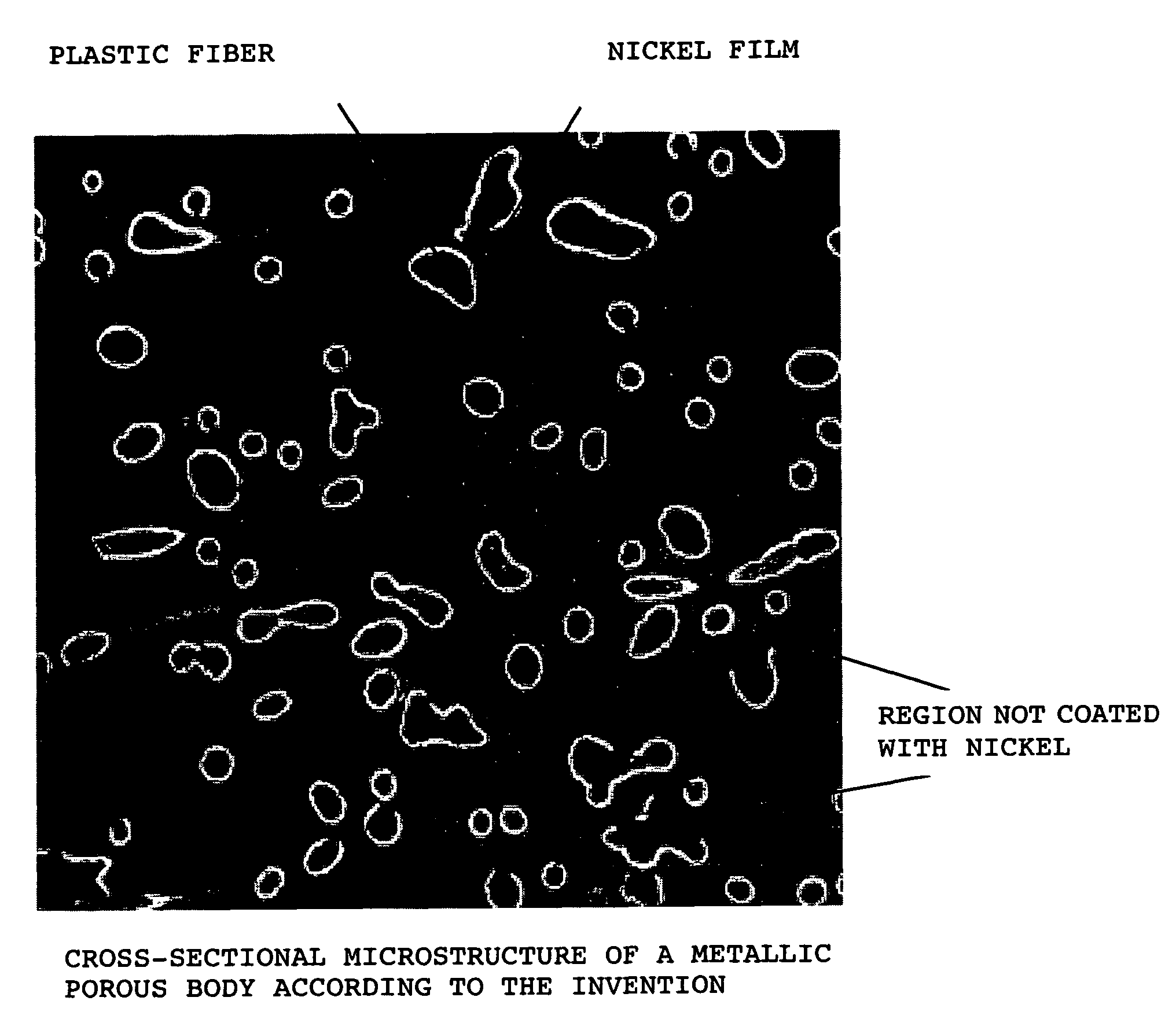
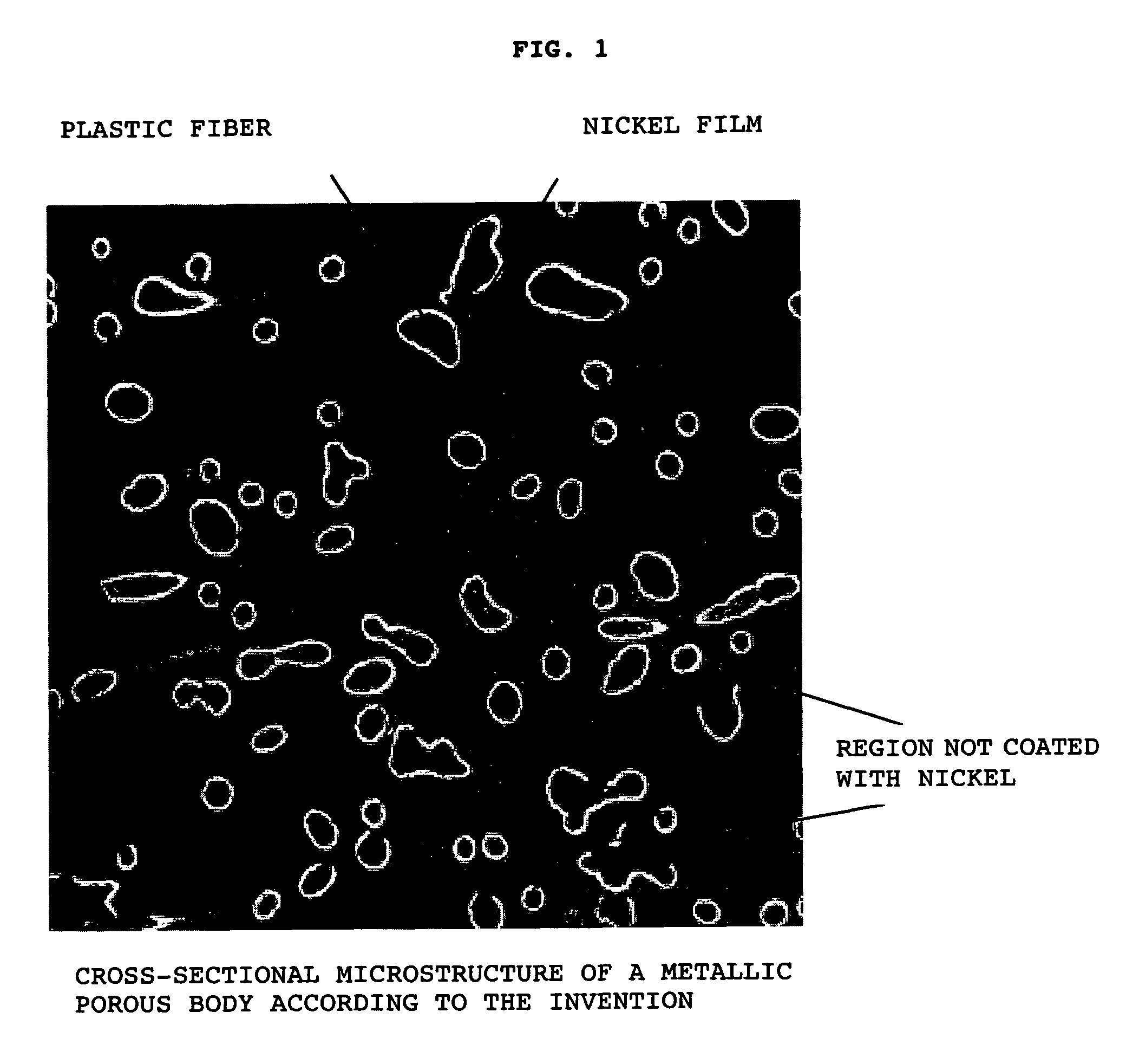
[0082]Unwoven fabric material having a 30% cumulative volume of pore size (D30) of 36 μm and comprising PP / PE composite fiber with a fiber diameter of 2.2 dtex and a core / sheath ratio of 1 / 1 was used as the plastic fiber. A conduction treatment was carried out on this unwoven fabric by forming thereon a 0.8 g / m2 nickel film by sputtering. The fiber surface was thereafter coated with nickel by electroplating to produce individual metallic porous body electrode substrates designated as Nos. 3 to 10. Table 1 below shows the areal densities, the nickel film coverage ratios measured from the cross-sectional structures, and the electrical resistance values of the produced metallic porous bodies with unwoven fabric structure.
[0083]
TABLE 1areal densityaverage coverageelectricalsample(g / m2)ratio by theresistance *1No.nickel film (%)(mΩ)1150761952150811493150861244150921205150981136 5096210710096155820096739300965610 4009643*1 Electrical resistance value for the area of 10 mm wide and 100 mm ...
example 2
[0089]Conduction treatment, in which a 1.5 g / m2 nickel film was formed by sputtering, was carried out on each of the unwoven fabrics Nos. 11 to 18 specified in Table 3 below. This treatment was performed so as to be an average coverage ratio of 95% thus the respective metallic porous body electrode substrates were obtained. The electrical resistance of each of the obtained substrates is shown in Table 3. The nickel areal density was 180 g / m2 for all of these metallic porous body substrates.
[0090]
TABLE 3PP (core) / PE (sheath)Cumulativeratio of the fibervolume ofElectricalSample(3.3 dtex) in thepore sizeresistance *1No.unwoven fabric(%) (D30)(mΩ)111 / 041192125 / 141165132 / 141103141 / 14189151 / 11487161 / 1110 89171 / 24183181 / 44178*1 Electrical resistance value for the area of 10 mm wide and 100 mm long.
[0091]Nickel-hydrogen batteries were fabricated in the same way as Example 1 using the substrates of Nos. 11 to 18 described in Table 3. As in Example 1, the individual batteries were assigned ba...
example 3
[0094]Unwoven fabric with a two-layer structure was fabricated as the plastic fiber; the two-layer structure was composed of a higher density layer with a thickness of 0.1 mm and a weight per area of 40 g / m2 that used PP / PE composite fiber with a core / sheath ratio of 3 / 7 and a fiber diameter of 0.8 dtex, and also composed of a lower density layer with a thickness of 0.7 mm and a weight per area of 35 g / m2 that used PP / PE composite fiber with a core / sheath ratio of 5 / 5 and a fiber diameter of 3.6 dtex. This unwoven fabric was given conductivity by forming a 1.8 g / m2 nickel film by sputtering. The fiber surface was thereafter coated with nickel by electroplating to produce collectors comprising individual metallic porous bodies of Nos. 21 to 25. The densities, the nickel film coverage ratios measured from the cross-sectional structures, and the electrical resistance values are shown in Table 5 below as for the fabricated metallic porous bodies with unwoven fabric structure.
[0095]
TABLE...
PUM
| Property | Measurement | Unit |
|---|---|---|
| pore size | aaaaa | aaaaa |
| density | aaaaa | aaaaa |
| density | aaaaa | aaaaa |
Abstract
Description
Claims
Application Information
 - R&D Engineer
- R&D Manager
- IP Professional
- Industry Leading Data Capabilities
- Powerful AI technology
- Patent DNA Extraction
Browse by: Latest US Patents, China's latest patents, Technical Efficacy Thesaurus, Application Domain, Technology Topic, Popular Technical Reports.
© 2024 PatSnap. All rights reserved.Legal|Privacy policy|Modern Slavery Act Transparency Statement|Sitemap|About US| Contact US: help@patsnap.com