
Elastic wave filter

a filter and elastic wave technology, applied in piezoelectric/electrostrictive/magnetostrictive devices, piezoelectric/electrostriction/magnetostriction machines, electrical equipment, etc., can solve the problems of large ohmic loss, unrealistic, and deterioration of the pass band of the filter, so as to reduce the size of the elastic wave filter and shorten the signal line

Inactive Publication Date: 2011-08-02
NIHON DEMPA KOGYO CO LTD
View PDF15 Cites 2 Cited by
  • Summary
  • Abstract
  • Description
  • Claims
  • Application Information

AI Technical Summary

Benefits of technology

[0013]The present invention has been achieved under the above-described circumstances, and an object thereof is to provide an elastic wave filter capable of suppressing deterioration of a pass band and capable of realizing downsizing.
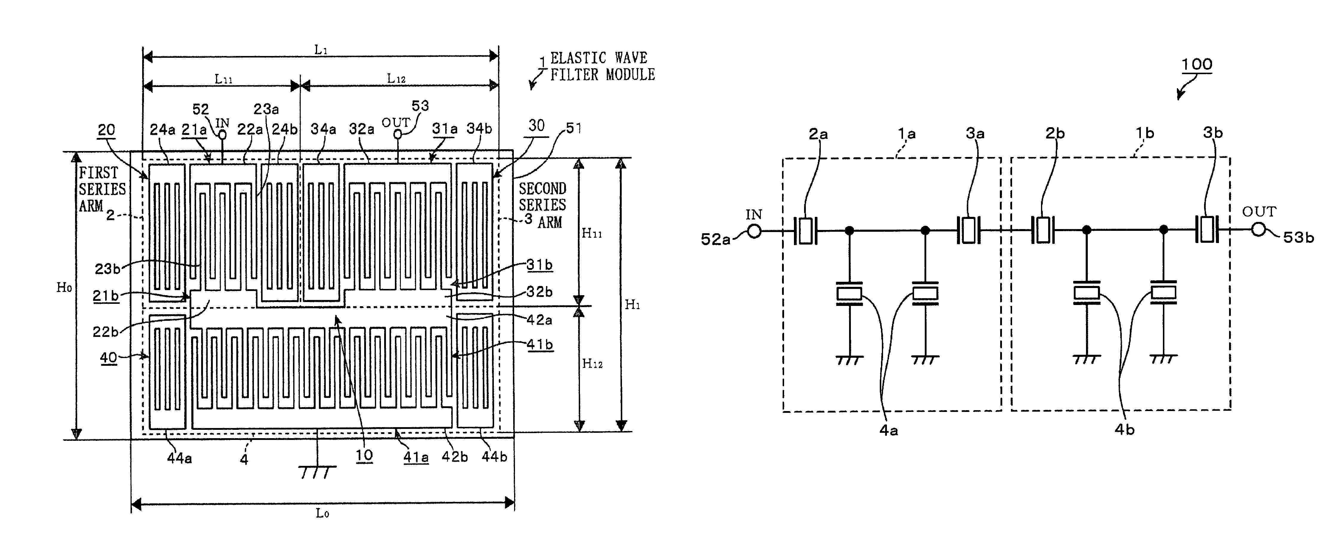
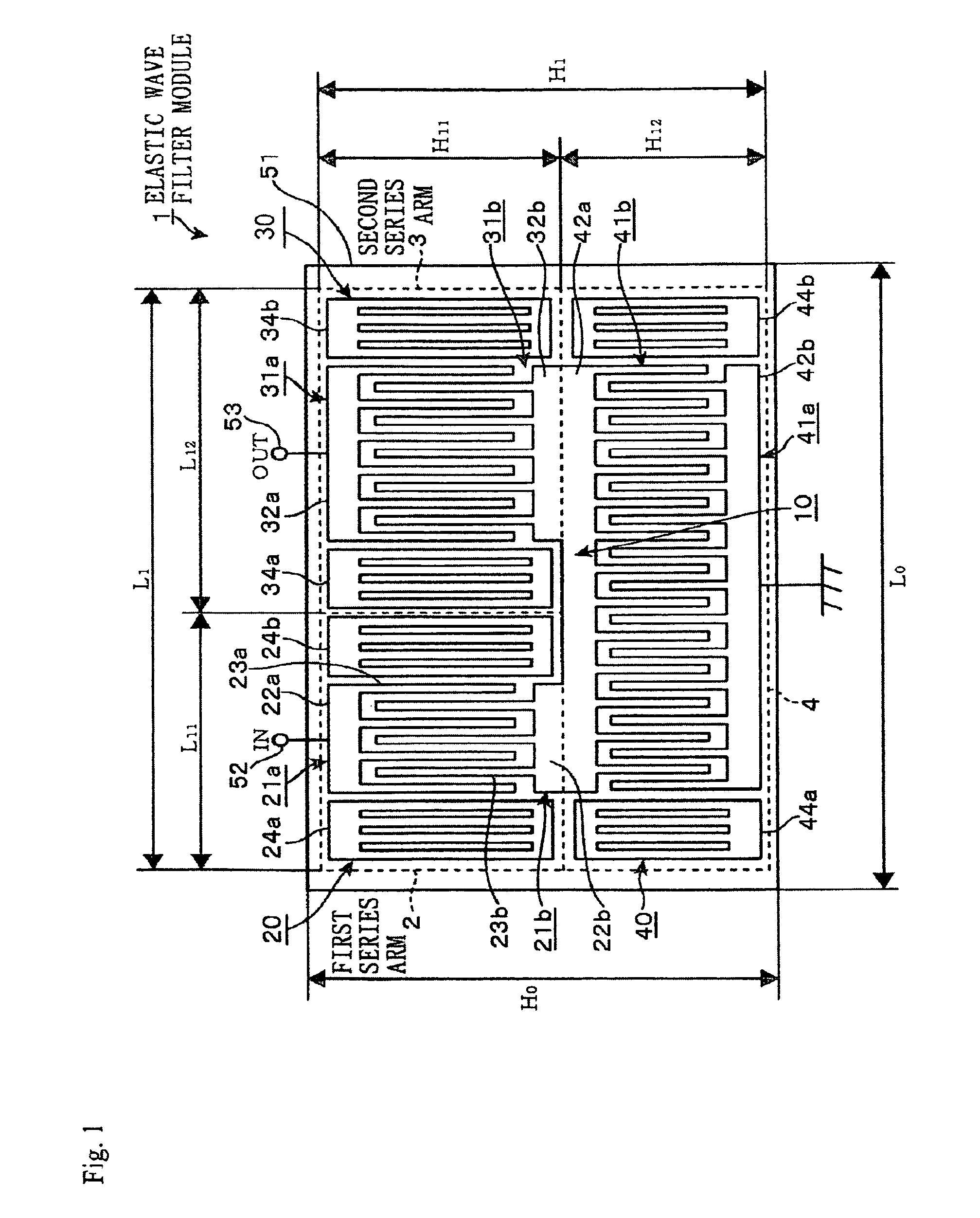
[0030]According to the present invention, since two elastic wave resonators are arranged adjacent to each other in the lateral direction out of three elastic wave resonators composing the first and the second series arms and the parallel arm connected each other at a common connection point and the remaining one is positioned on the rear side of these rows, it is possible to place the bus bars of the respective elastic wave resonators connected to the common connection point close to each other. As a result, it becomes possible to shorten the signal line to become a connection point of these bus bars, it is possible to keep the empty space created by routing through the signal line small and to further downsize the elastic wave filter. When bus bars of the respective elastic wave resonators are made in common to use as the signal line, it becomes possible to cancel the empty space caused by routing through the signal line and to further reduce the elastic wave filter.
[0031]Furthermore, by shortening the signal lines as described above and using the bus bar for the signal line, it becomes possible to suppress deterioration of the pass band of the filter due to signal loss and increase of the parasitic capacitance caused by the ohmic loss, which contributes to improvement in performance of the filter, compared with the case of routing through a wide and long signal line.

Problems solved by technology

In addition, as a problem separated from the above-described empty spaces S1 through S4, there comes up another problem in a manner that when the signal line 132 having a large area shown in FIG. 10 is adopted from the viewpoint of preventing the ohmic loss, parasitic capacitance of the signal line 132 also increases, which leads to deterioration of a pass band of the filter.
However, electrode fingers provided in a large number to a reflector are very thin of about several μm for instance, and the use of such a thin electrode finger as the signal line may lead to a large ohmic loss and it is not realistic.
On the other hand, since the area of the whole reflector is large even when compared with a conventional signal line, the parasitic capacitance becomes large and the bass band of the filter is deteriorated.

Method used


Image

  • Elastic wave filter
  • Elastic wave filter
  • Elastic wave filter

Examples


example 1

[0081]The passing characteristics of the resonator module 1 shown in FIG. 1 are simulated.

[0082]The conditions of the simulation

[0083]piezoelectric substrate: LiTaO3

[0084]chip size: 1.2 mm×0.5 mm

Comparison Example 1

[0085]The passing characteristics of the resonator module 110 shown in FIG. 10 are simulated.

[0086]The conditions of the simulation

[0087]piezoelectric substrate: LiTaO3

[0088]chip size: 1.0 mm×1.5 mm

[0089](The Result of the Simulation)

[0090]The simulation result is shown in FIG. 7A and FIG. 7B.

[0091]FIG. 7A is an all over view of the passing characteristics of the respective resonator modules 1 and 110, and FIG. 7B shows an enlarged view of the passing characteristics in the pass band. The horizontal axes of the respective drawings are frequencies [MHz], the vertical axes are attenuation amounts [dB], a solid line in the drawing indicates the simulation result of (Example 1), and a broken line indicates the simulation result of

example 2

[0095]The passing characteristics of the resonator module 1 shown in FIG. 1 are simulated.

[0096]The conditions of the simulation

[0097]piezoelectric substrate: LiTaO3

[0098]chip size: 1.2 mm×0.5 mm


PUM


Abstract

The object of the present invention is to provide an elastic wave filter capable of suppressing deterioration of a pass band and realizing to downsize. In the elastic wave filter of the present invention provided with a circuit, to which elastic wave resonators of a first series arm, a second series arm and a parallel wave are connected, the first series arm and one out of the second series arm and the parallel arm are arranged in the lateral direction in a row to be adjacent to each other, and the other out of the second series arm and the parallel arm is disposed on the rear side of the row, and prescribed bus bars in the first series arm, the second series arm and the parallel arm are arranged on the common connection point side.

Description

BACKGROUND OF THE INVENTION[0001]1. Field of the Invention[0002]The present invention relates to an elastic wave filter provided with an elastic wave resonator such as a surface acoustic wave (SAW) resonator or the like.[0003]2. Description of the Related Art[0004]For the elastic wave filter installed on a mobile terminal such as a cellular phone or the like and performing distinction of frequency signals, a ladder type filter 100 having a configuration such that a constant-K circuit taking a series arm 101 and a parallel arm 102 for a base section as shown in FIG. 9 is formed, and plural sets of the base section 103 of the constant-K circuit are connected in series is adopted. Then, it becomes possible to allow a signal having a specific frequency to pass through by making a resonance frequency of the series arm 101 and an anti-resonance frequency of the parallel arm 102 in the base section 103 nearly consistent with each other.[0005]For the series arm 101 and the parallel arm 102 ...

Claims


Application Information

Patent Timeline
Patent Type & Authority Patents(United States)
IPC IPC(8): H03H9/64
CPCH03H9/6483
Inventor SAKURABA, YOICHI
Owner NIHON DEMPA KOGYO CO LTD
Learn More