Eureka AIR delivers breakthrough ideas for toughest innovation challenges, trusted by R&D personnel around the world.

Flexible graphite/metal multilayer gaskets suited to high-temperature service conditions

a multi-layer, graphite/metal technology, applied in the direction of sealing, natural mineral layered products, other domestic articles, etc., can solve the problems of difficult to produce gaskets in heavy thicknesses, difficult to handle, and relatively easy to tear, so as to facilitate the cutting of gaskets

Inactive Publication Date: 2011-08-02
CARBONE LORRAINE COMPOSANTS GENNEVILLIERS
View PDF23 Cites 25 Cited by
  • Summary
  • Abstract
  • Description
  • Claims
  • Application Information

AI Technical Summary

Benefits of technology

"The present invention relates to a composite plate made of flexible graphite foils and perforated metal reinforcing foils with spurs. The composite plate has alternating layers of flexible graphite foils and perforated metal reinforcing foils. The flexible graphite foils have a thickness of 2 mm or less, and the composite plate has a density per unit area of at most 2.34 kg / m2. The perforated metal reinforcing foils have spurs with a height that does not exceed 1.3 times the thickness of the thinnest flexible graphite layer to which it is attached. The invention also includes a flat gasket made from the composite plate and a use of the gasket at temperatures not exceeding 600°C. The technical effects of the invention include improved thermal insulation, reduced weight, and improved mechanical properties."

Problems solved by technology

They are difficult to handle, they tear relatively easily, and it is difficult to produce them in heavy thicknesses.
These gaskets are also stressed in the direction parallel to the layers that form them, due to the poorly distributed, heavy compressive stress over the entire surface of the gasket; this phenomenon is called “the toe-in of the clamp.” Thus, they may have a creep problem, particularly at a high-operating temperature, when the thermal expansion deforms the geometry of the clamp.
Creep is therefore likely to limit their lifespan and the seal of the system of which they are a part.
To fasten a flexible graphite foil onto a metal plate or foil, glues or adhesives can be used conventionally, but the latter cannot guarantee mechanical strength beyond 300° C. The patents EP 616 884, U.S. Pat. Nos. 5,509,993 and 6,962,349 (Sigri Great Lakes Carbon AG) disclose the use of substances that alter the interface between the metal and the graphite, but that are not glues, such as certain organosilicon compounds, perfluorinated compounds or metallic soaps.
This technique, however, is very expensive to implement because it is not very productive, and it does not guarantee a sufficient degree of mechanical strength for the assembly beyond 400° C.
However, as taught by U.S. Pat. No 5,509,993 cited above, the perforation of the dome-shaped plates causes local stresses in the plate, which can lead to ruptures under load.
However, the stacks of flexible graphite foils attached to metal plates still have some weak points.
First of all, the perforated metal reinforcements in strip thicknesses greater than or equal to 100 μm make it more difficult to cut out the gaskets, an operation that makes it possible to obtain the desired geometries from flat foils.
Furthermore, they require production methods that are more difficult to implement than the simple roll-bonding used to bond together a perforated foil and a flexible graphite foil.
On the other hand, glue-less assembly methods also exist, but these methods are likewise complex, because they make use of hot-pressing methods as well as the application of a very slight thickness of chemical products that alter the surface.
In any event, roll-bonding with a perforated plate seems to be the most economical continuous assembly method, but has significant disadvantages such as the difficulty of cutting via conventional means.
Generally, when the operating temperature exceeds 400° C., and when the pressures of the fluids being sealed off are too great, flat gaskets cut out of composite flexible graphite-based plates must be replaced by more reliable but also more costly solutions; however, these solutions are less dimensionally flexible, such as spiral gaskets, serrated gaskets and other metal gaskets.

Method used


Image

  • Flexible graphite/metal multilayer gaskets suited to high-temperature service conditions
  • Flexible graphite/metal multilayer gaskets suited to high-temperature service conditions
  • Flexible graphite/metal multilayer gaskets suited to high-temperature service conditions

Examples


example 1

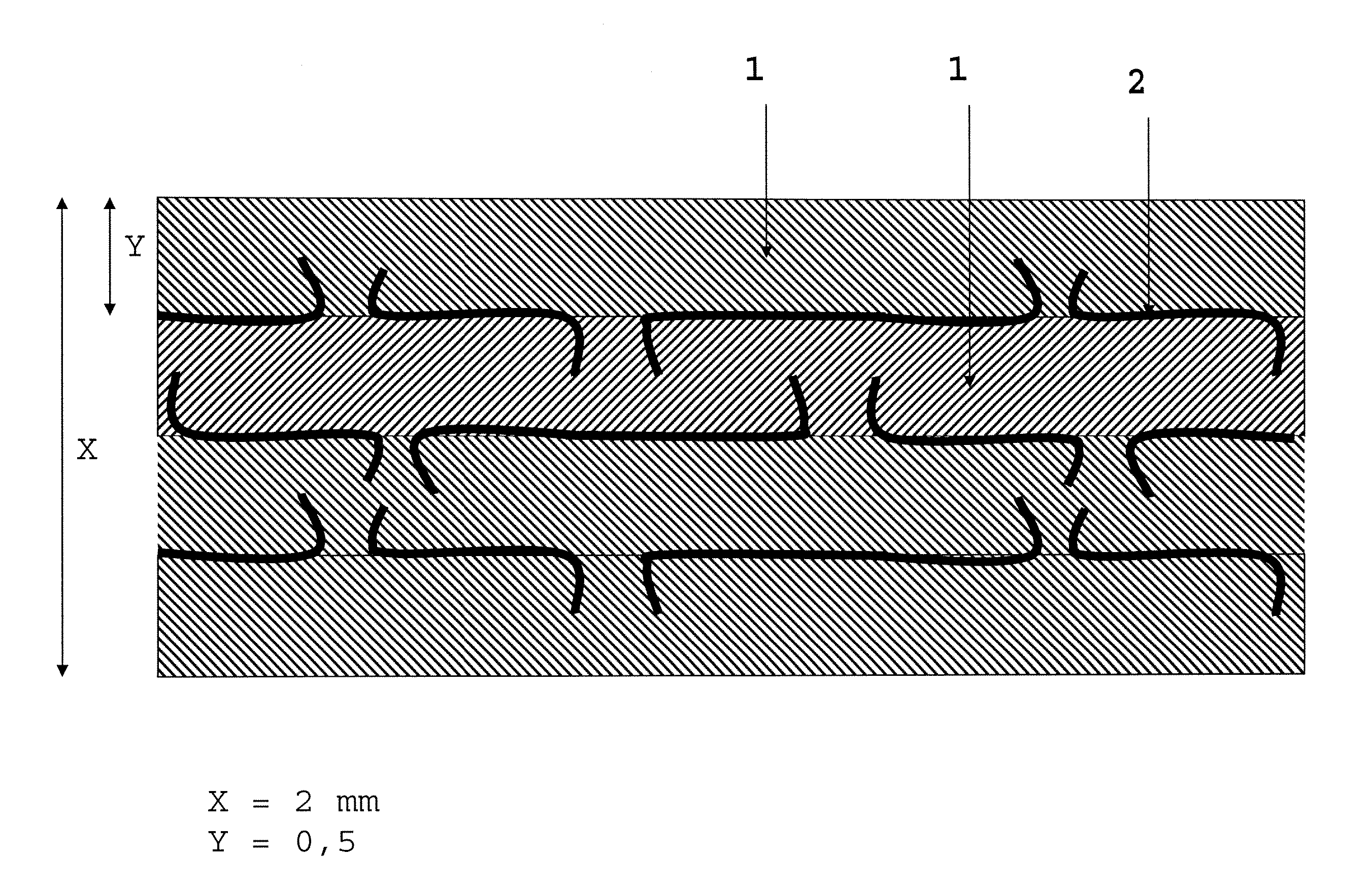
[0070]A composite plate was made by alternately stacking four flexible graphite foils produced by the Carbone Lorraine Corporation, Papyex® 1600° grade, with a density of 1 g / cm3, a thickness of 0.5 mm (foils supplied in rolls of 1 m in width and 300 m in length), and three stainless steel foils, grade 316, with a thickness of 50 micrometers, perforations via 1.2 mm diameter, evenly distributed holes with a density of 4 perforations per cm2, and a height of the spurs resulting from the perforations of 650 micrometers above the plane of the foils (1 m wide and 300 mm long foils supplied in reels). The final thickness of the gasket is 2 mm.

[0071]After the gasket has been kept at 550° C. for 48 hours, under a prestressing of 20 MPa, the measurement of the maximum permissible stress QSmax at 550° C. yields a value close to 200 MPa, according to the standard EN 13555.

example 2

[0072]A composite plate was made by alternately stacking four flexible graphite foils produced by the Carbone Lorraine Corporation, Papyex® 1980 grade, with a density of 1 g / cm3, a thickness of 0.5 mm (foils supplied in rolls of 1 m in width and 300 m in length), and three stainless steel foils, grade 316, with a thickness of 50 micrometers, perforations via 1.2 mm diameter, evenly distributed holes with a density of 4 perforations per cm2, and a height of the spurs resulting from the perforations of 650 micrometers above the plane of the foils (1 m wide and 300 mm long foils supplied in reels). These steel foils are coated on both sides with a 5 μm thickness of nitrile rubber.

[0073]Composite plates have been made via continuous roll-bonding of seven layers (4 layers of flexible graphite, 3 perforated metal layers), with a total thickness of approximately 2 mm. At the end of the roll-bonding operation, the products are kept flat and cut into plates measuring 1 m×1 m.

[0074]Some of th...

example 3

[0087]Conventional multilayer structures (such as: Sigraflex Select and HD, or Papyex® HP) do not further make it possible to combine a seal conforming to the standard VDI 2440 (TA Luft), with a mechanical strength at high temperatures such as this and high mechanical performance, without the addition of a metal ring sealing off the internal section of the gasket, as described in U.S. Pat. No 6,962,349, which is incorporated herein by reference in its entirety.

[0088]The gasket being cut to size from the plate by the user does not then make it possible to guarantee the leakage level for the cut-out gasket that is required by regulations, without mastering the method of adding the ring.

[0089]However, it can be noted that the structure according to the present invention, combined with using the metal ring, makes it possible to obtain results conforming to the standard VDI 2440 (TA Luft), even without the addition of functionalizing agents, and this is so despite the fact that all of th...


PUM

PropertyMeasurementUnit
thicknessaaaaaaaaaa
diameteraaaaaaaaaa
diameteraaaaaaaaaa

Abstract

The present invention relates generally to a composite plate produced by an alternating stack of (n+1) flexible graphite foils and (n) perforated metal reinforcing foils with spurs (where n≧2). The thicknesses of the flexible graphite foils used are preferably such that any 2 mm slice of thickness of the composite plate comprises at least 3 layers of flexible graphite, and has a graphite density per unit area of at least 2.34 kg / m2. For each perforated metal reinforcing foil, the spurs present on the foil generally have a height in relation to the surface of that foil that does not exceed about 1.3 times the thickness of the thinnest of the flexible graphite layers to which it is attached. A composite plate of the present invention enables the manufacture of gaskets that resist temperatures up to 550° C. under continuous service.

Description

CROSS REFERENCE TO RELATED APPLICATION[0001]This application claims priority to FR 0601243, filed Feb. 10, 2006, the content of which is incorporated herein by reference in its entirety.BACKGROUND OF THE INVENTION[0002]1. Field of the Invention[0003]The present invention relates generally to the field of manufacturing flat gaskets produced by alternating stacks of flexible graphite and perforated metal foils, which are capable of withstanding high-temperature conditions of 300° C. or more, for example, without undergoing deterioration in their quality, even under very high clamping stresses.[0004]2. Description of Related Art[0005]Flexible graphite is fabricated by thermal expansion of graphite (most often in the form of flakes), into which atoms or molecules have been inserted following attack in an acid medium; the material thereby obtained has a very low mass density and possesses the property of self-agglomerating without any binder, via a simple mechanical effect. In this way, ...

Claims


Application Information

Patent Timeline
Patent Type & Authority Patents(United States)
IPC IPC(8): B32B9/00F16J15/02B32B3/10B32B7/02B32B7/022
CPCB32B15/20B32B7/02B32B9/007B32B9/041B32B15/06B32B15/08B32B15/085B32B15/18B32B25/04B32B27/32B32B27/322B32B3/266C04B37/021F16J15/122Y10T428/2495B32B2274/00B32B2307/72B32B2581/00C04B2237/363C04B2237/405C04B2237/704C04B2237/706Y10S277/936Y10S277/939Y10S277/945Y10T428/24992Y10T428/24331Y10T428/30Y10T428/31699Y10T83/0524Y10T83/04Y10T428/31678Y10T428/31692B32B7/022
Inventor POTIER, ALEXANDRE
Owner CARBONE LORRAINE COMPOSANTS GENNEVILLIERS
Why Eureka
Eureka Blog
Learn More